Page 9
Downflow Applications
The Lennox G24M furnace is shipped in the upflow configĆ
uration and must be converted for downflow installation.
Refer to figure 6 and the following steps to convert the unit
for downflow installation:
1 - Place unit on its back and remove access panel.
2 - Disconnect wire harness jackplug from control board.
3 - Disconnect ignition lead from control board.
4 - Remove four screws securing cabinet top cap to cabiĆ
net.
5 - Remove four screws holding heat exchanger assemĆ
bly in place. Slide heat exchanger out through top of
cabinet.
6 - Rotate heat exchanger 180
o
and slide back into cabiĆ
net through top. Resecure using four screws.
7 - Remove four screws securing cabinet bottom piece
to cabinet. Replace with cabinet top cap.
8 - Use four screws to install cabinet bottom piece where
cabinet top was.
9 - Reconnect ignition lead to control board.
10- Reconnect wire harness jackplug to control board.
11- Replace unit access panel.
12- Use cord clip located on right side of furnace to
hold wiring away from hot surfaces in heating
compartment. Install two #10 sheet metal screws in
cabinet top to provide a better air seal.
In downflow applications, the unit can be installed in three difĆ
ferent ways: on non-combustible flooring, on combustible
floor using an additive base, or on a reverse-flow cooling cabĆ
inet. Do not drag unit across floor.
Allow clearances to combustible materials as outlined on
unit rating plate. Minimum clearances for closet or alcove
installations are outlined in figure 7.
NC**
DOWNFLOW APPLICATION
INSTALLATION CLEARANCES
VENT
CONNECTOR
TYPE
TYPE C TYPE B1
TOP 1 in. (25mm) 1 in. (25mm)
*FRONT 2 in. (51mm) 2 in. (51mm)
BACK
SIDES
VENT 6 in. (152mm) 1 in. (25mm)
NC - Non-combustible floor
*Front clearance in alcove installation must be
a min. of 24 in. (610mm) for service access.
**With additive base on combustible floor.
BOTTOM NC**
1 in. (25mm) 1 in. (25mm)
1 in. (25mm) 1 in. (25mm)
TOP
BOTTOM
RIGHT
SIDE
LEFT
SIDE
FIGURE 7
A separate downflow filter kit is available for use in downĆ
flow applications.
A-Installation on Non-Combustible Flooring
1 - Cut floor opening keeping in mind the clearances
listed on the unit rating plate. Also, keep in mind gas
supply and electrical supply, vent connections and
sufficient installation and service clearances. See
table 1 for correct floor opening size.
TABLE 1
NONCOMBUSTIBLE FLOOR OPENING
UNIT
Front to Rear Side to Side
in mm in mm
G24M-45/60/75 502 388
NOTE-Floor opening dimensions listed are 1/4" (6mm) larger than
unit openings.
19-3/4 15-1/4
G24M-100/120 502 47719-3/4 18-3/4
G24M-140 502 54619-3/4 21-1/2
2 - Flange warm air plenum and lower into opening.
3 - Set unit over plenum.
4 - Check to see that an adequate seal is made.
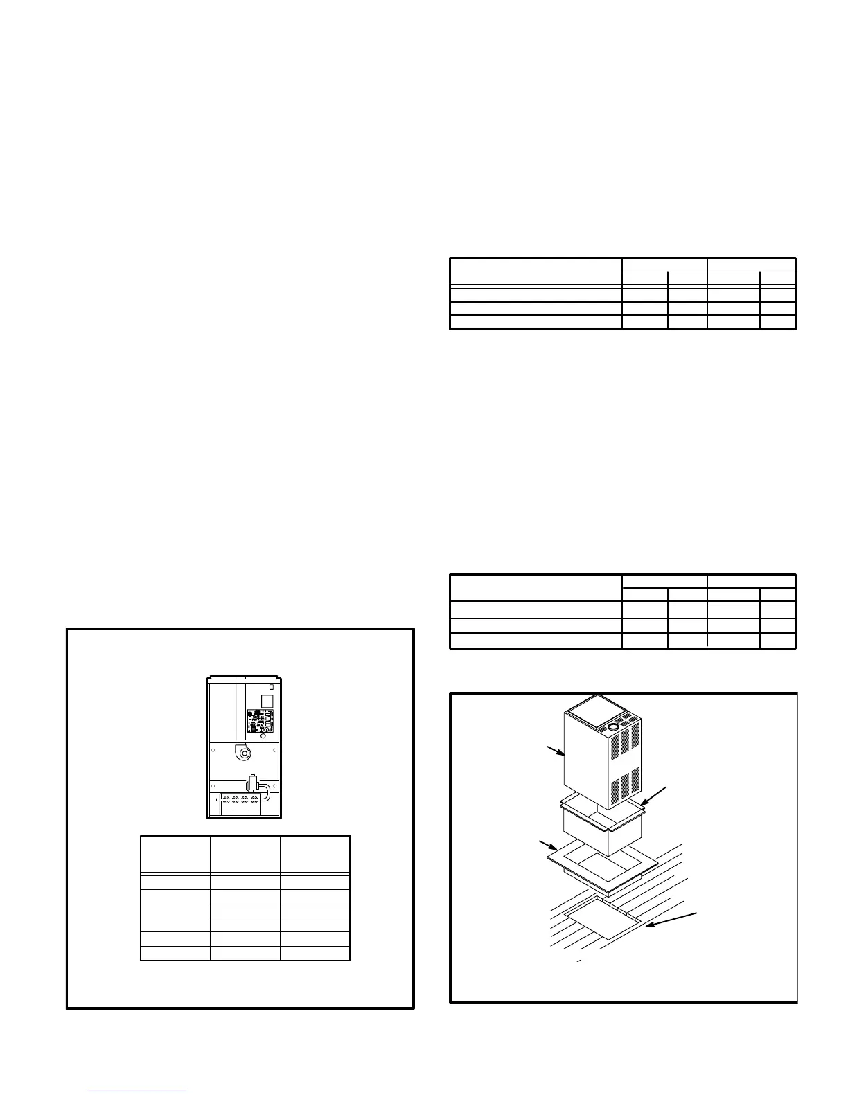
B-Installation on Combustible Flooring
1 - When unit is installed on a combustible floor, an addiĆ
tive base (ordered separately) must be installed beĆ
tween the furnace and the floor. See table 2 for openĆ
ing size to cut in the floor.
TABLE 2
ADDITIVE BASE FLOOR OPENING
UNIT
Front to Rear Side to Side
in mm in mm
G24M-45/60/75 556 440
NOTE-Floor opening dimensions listed are 1/4" (6mm) larger than
additive base openings.
21-7/8 17-5/16
G24M-100/120
556 52821-7/8 20-3/4
G24M-140
556 59721-7/8 23-1/2
G24M UNIT
SUPPLY AIR
PLENUM
ADDITIVE
BASE
PROPERLY
SIZED FLOOR
OPENING
1. Cut correct size floor opening
2. Set additive base into opening.
3. Set supply air plenum into additive base.
4. Set unit.
FIGURE 8

 Loading...


