Page 8
Setting Equipment
The Lennox G24M multi-position gas furnace can be
installed as shipped in upflow position or in horizontal
position with right-hand or left-hand discharge. The furĆ
nace can easily be converted for downflow applications.
Select a location that allows for required clearances
listed on the unit rating plate. Also consider gas supply
connections, electrical supply, vent connection and
installation and service clearances [24 inches (610 mm)
at unit front].
NOTE - 1/3 and 1/2 hp blower motors are equipped with eiĆ
ther four flexible mounting legs or three flexible legs and
one rigid leg. The rigid leg is equipped with a shipping bolt
and a flat white plastic washer (rather than the rubber
mounting grommet used with a flexible mounting leg). This
shipping bolt and flat washer must be removed before the
furnace is put into operation. Once the shipping bolt and
washer are removed, the rigid leg will not touch the fan
housing.
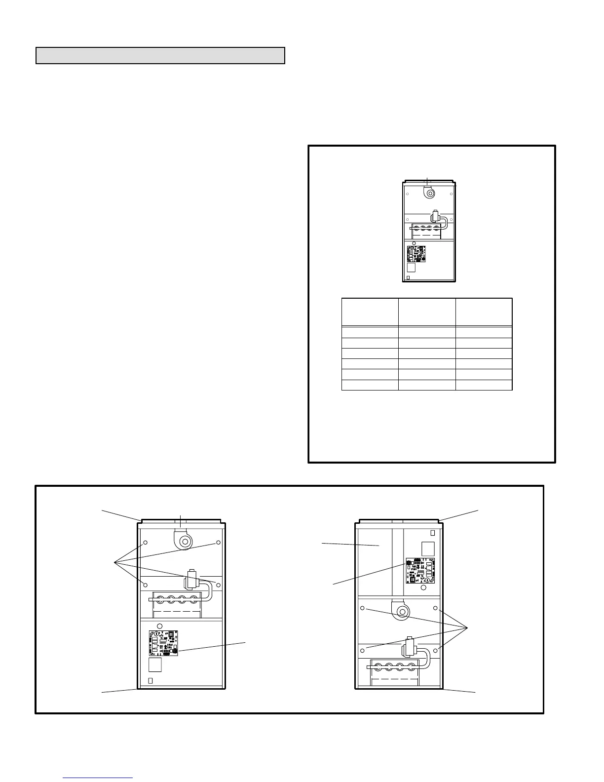
Upflow Applications
The Lennox G24M furnace is shipped in a standard upflow
position. Level the furnace using shims or leveling bolts. AlĆ
low for clearances to combustible materials as indicated on
the unit rating plate. Minimum clearances for closet or alĆ
cove installations are shown in figure 5.
In upflow applications, return air can be brought in through
the bottom or either side of the furnace. If a furnace with
bottom return air is installed on a platform, make an airtight
seal between the bottom of the furnace and the platform to
ensure proper and safe operation.
Knockouts are provided on both sides of the furnace cabinet
for installations with side return air. When side return air is
used, seal the bottom of the furnace using the panel provided.
An upflow filter rack is available and must be ordered sepaĆ
rately. The adjustable rack can be installed beneath the furĆ
nace (flush with cabinet edges) for bottom return air apĆ
plications or on the side of the furnace for side return air.
NOTE - A sheet metal filter puller is provided along with the
filter kit. In bottom return air applications, filter puller must
be installed between frame and filter to hold filter in place.
6 in. (152 mm)
0
0
2 in. (51 mm)
1 in. (25 mm)
Upflow Application
Installation Clearances
Vent
Connector
Type
Type C
Type B1
TOP 1 in. (25 mm)
*FRONT 2 in. (51 mm)
BACK 0
SIDES 0
VENT 1 in. (25 mm)
0**FLOOR 0**
*Front clearance in alcove installation must be 24 in. (610
mm). Maintain a minimum of 24 in. (610 mm) for front service
access.
** For installations on a combustible floor, do not install the
furnace directly on carpeting, tile or other combustible mateĆ
rials other than wood flooring.
RIGHT
SIDE
LEFT
SIDE
TOP
BOTTOM
FIGURE 5
UNIT CONVERSION FOR DOWNFLOW APPLICATION
REMOVE
TOP CAP
REMOVE
BOTTOM
REMOVE
FOUR
SCREWS
DISCONNECT
WIRE HARNESS AT
CONTROL BOARD
CONNECTOR
DISCONNECT
IGNITOR & SENSOR
LEADS
REINSTALL
TOP CAP ON
UNIT BOTTOM
REINSTALL
BOTTOM
ON UNIT
TOP
ROTATE HEAT
EXCHANGER
& REINSTALL
RECONNECT
IGNITOR & SENSOR
LEADS
UPFLOW CONFIGURATION DOWNFLOW CONFIGURATION
SINGLE-WALLED VENT
PIPE FROM COMBUSTION
AIR FAN FLUE ADAPTER TO
FURNACE FLUE OUTLET
(Furnished by installer)
RECONNECT WIRE
HARNESS AT
CONTROL BOARD
CONNECTOR
FIGURE 6

 Loading...


