Page 2
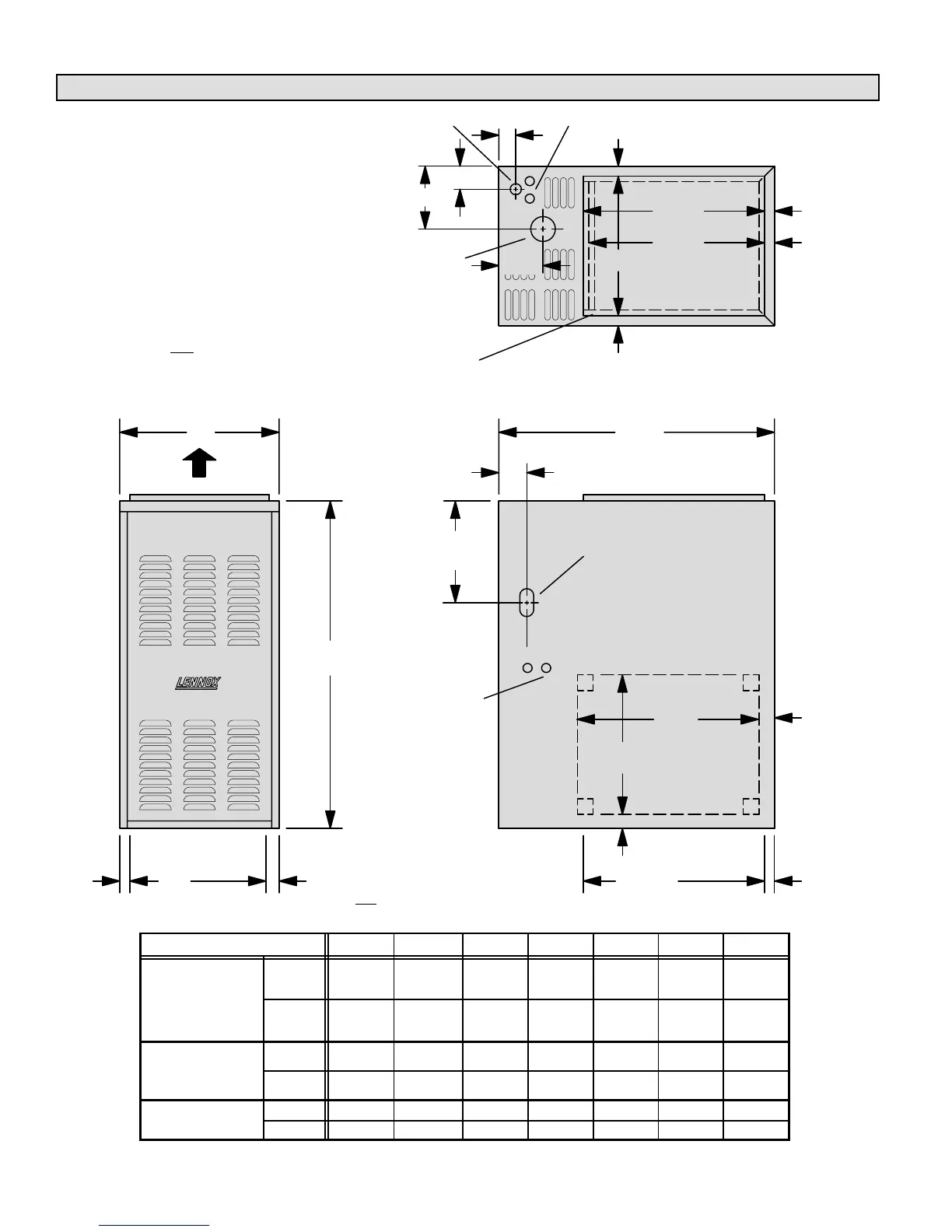
G24M Unit Dimensions - inches (mm)
SUPPLY
AIR
OPENING
A
B
*C
**C
RETURN AIR
KNOCKOUT
(Either Side)
Return Air
Opening
Return Air
Opening
GAS PIPING
INLET
(Both Sides)
ELECTRICAL
INLETS
(Both Sides)
FLUE
OUTLET
D
AIR FLOW
FRONT VIEW SIDE VIEW
TOP VIEW
F Left Side
G Right Side
2 (51)
29Ć5/8
(752)
*19Ć1/2
(495)
**19Ć1/2
(495)
19Ć1/2
(495)
15
(381)
2 (51)
E
1
(25)
1
(25)
1
(25)
1
(25)
1
(25)
1
(25)
1
(25)
GAS PIPING
INLET
ELECTRICAL INLETS
(Top & Bottom)
3/4 (19)
4Ć1/4
(105)
*19
(483)
1
(25)
Unit shown in upflow position. Rotate 1805 for
downflow applications and 905 clockwise or
counterclockwise for horizontal applications.
*NOTE – The supply air opening is equipped with a 3/4 inch (19 mm) scored
flange that may be bent 90_ for plenum connection. The dimensions shown
were taken after
the flange was bent.
The double scored flange at the front of the supply air opening may be
bent for a total opening dimension (front to rear) of either 19-1/2 inches
(495 mm) or 19 inches (483 mm).
**NOTE – The return air opening is
equipped with a 3/4 inch (19 mm) scored
flange that may be bent 90_ for plenum con-
nection. The dimensions shown were taken
after
the flange was bent.
Model No.
A B C D E F G
G24M2Ć45
G24M2Ć60
24M2Ć7
in. 17 36Ć1/4 15 6Ć3/4 2Ć7/16 11Ć1/2 6Ć1/2
Ć
G24M3Ć60
G24M3Ć75
G24M4Ć75
mm 432 921 381 171 62 293 165
G24M3/4Ć100
G24M3/4Ć120
in. 20Ć1/2 39 18Ć1/2 8Ć3/8 4Ć1/4 13 8
G24M4/5Ć100
G24M4/5Ć120
mm 521 991 470 213 108 331 203
in. 23Ć1/4 39 21Ć1/4 9-3/4 4Ć1/4 12Ć31/32 7Ć3/32
G24M4/5Ć140
mm 591 991 540 248 108 329 180

 Loading...


