Page 21
7 - Electrically ground the unit according to local codes or,
in the absence of local codes, according to the current
National Electric Code (ANSI/NFPA No. 70) for the
USA and current Canadian Electric Code part 1 (CSA
standard C22.1) for Canada.
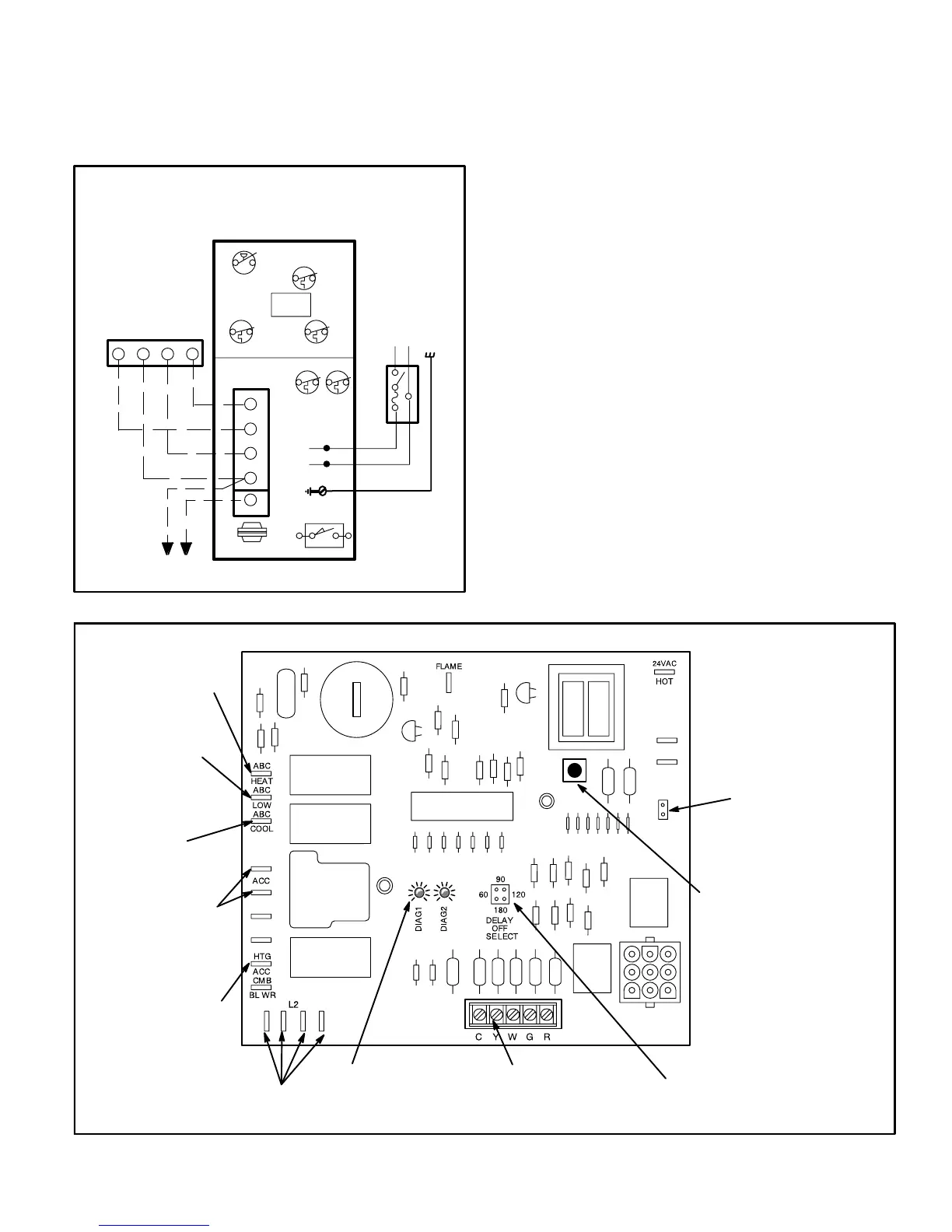
TYPICAL G24M FIELD WIRING DIAGRAM
PRIMARY
LIMIT
PRESSURE
SWITCH
GAS
VALVE
FLAME ROLLOUT SWITCHES
SECONDARY
LIMITS
BLACK
WHITE
TRANSFORMER
R
G
W
Y
RGWY
CONTROL
BOARD
DOOR
INTERLOCK
L1
(L2)
N
FUSED OR
CIRCUIT BREAKER
DISCONNECT
(Furnished by
installer)
TO
COMPRESSOR
CONTACTOR
THERMOSTAT
C
GND
240V, 1PH, 50HZ
(240V, 1PH, 50HZ)
FIGURE 18
8 - Three 240 volt accessory terminals are provided on the
control board. Two are energized with the indoor blower
and one is energized with the combustion air blower.
Any accessory rated up to one amp can be connected
to the accessory terminals with the neutral leg of the cirĆ
cuit being connected to the 240 volt neutral wires.
9 - This unit is equipped with an integrated control board
that controls blower operation, fan off timings and igniĆ
tion. The board includes a terminal strip for thermostat
connections and two diagnostic LEDs. See figure 19 for
control board configuration. Diagnostic codes are given
in a chart at the back of this manual.
The red diagnostic button can be used to view the last
failure code.
10 - Refer to blower speed chart on wiring diagrams for
factoryĆset cooling, heating and continuous fan
speeds.
Systems using a cooling thermostat subbase may opĆ
erate the blower continuously (factory set at low
speed) through the thermostat FAN ON" switch. SysĆ
tems which do not include a cooling subbase require
a toggle switch which must be wired between termiĆ
nals R" and G" on the thermostat connection terminal
strip.
The blower motor will operate at the designated speed
during cooling or heating demand; however, when deĆ
mand is satisfied, blower speed will revert to selected
continuous speed.
EGC-3A INTEGRATED CONTROL BOARD
NEUTRAL
TERMINALS
ACCESSORY
TERMINALS
THERMOSTAT
TERMINAL STRIP
BLOWER TIME
ADJUSTMENT
JUMPER
HEATING SPEED
TAP TERMINAL
COOLING SPEED
TAP TERMINAL
CONTINUOUS FAN
TERMINAL
HEATING
ACCESSORY
TERMINAL
DIAGNOSTIC
LEDS
RED DIAGNOSTIC BUTTON
(Depress button and hold for
display of last failure code.)
DIAGNOSTIC CODE
ERASE JUMPER
(Remove power to control
and short pins for 10 secĆ
onds to erase previous
code.)
GND
L1
FIGURE 19

 Loading...


