Page 20
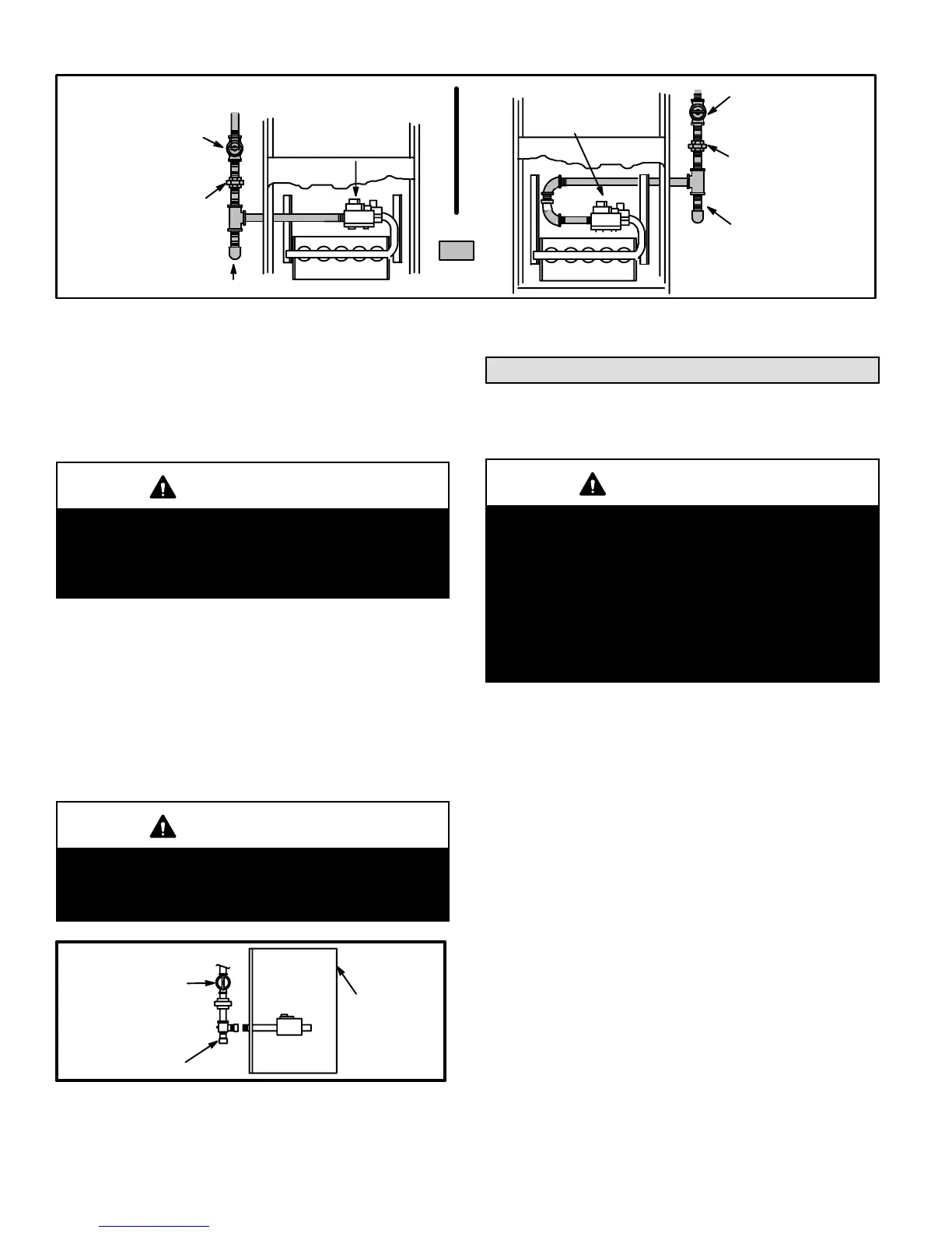
GROUND
JOINT
UNION
AUTOMATIC
GAS VALVE
(with manual
shut-off valve)
FIELD
PROVIDED
AND INSTALLED
GROUND
JOINT
UNION
Left Side Piping
(Standard)
Right Side Piping
(Alternate)
AUTOMATIC
GAS VALVE
(with manual
shut-off valve)
DRIP LEG
DRIP LEG
MANUAL
MAIN SHUT-OFF
VALVE
(With 1/8 in. NPT
Plugged Tap Shown)
MANUAL
MAIN SHUT-OFF
VALVE
(With 1/8 in. NPT
Plugged Tap
Shown)
FIGURE 16
Leak Check
After gas piping is completed, carefully check all piping
connections (factory- and field-installed) for gas leaks. Use
a leak detecting solution or other preferred means.
CAUTION
Some soaps used for leak detection are corrosive to
certain metals. Carefully rinse piping thoroughly afĆ
ter leak test has been completed. Do not use
matches, candles, flame or other sources of ignition
to check for gas leaks.
NOTE - In case emergency shutoff is required, shut off the
main manual gas valve and disconnect the main power to
the furnace. These devices should be properly labeled by
the installer.
The furnace must be isolated from the gas supply system
by closing its individual manual shutĆoff valve during any
pressure testing of the gas supply system at pressures
equal to or less than 1/2 psig (3.48 kPa).
IMPORTANT
When testing pressure of gas lines, gas valve must
be disconnected and isolated. See figure 17. Gas
valves can be damaged if subjected to more than 1/2
psig (3.48 kPa).
MANUAL MAIN
SHUT-OFF VALVE
WILL NOT HOLD
NORMAL TEST
PRESSURE
CAP
ISOLATE
GAS VALVE
FURNACE
FIGURE 17
Electrical
ELECTROSTATIC DISCHARGE (ESD)
Precautions and Procedures
CAUTION
Electrostatic discharge can affect electronic comĆ
ponents. Take precautions during furnace installaĆ
tion and service to protect the furnace's electronic
controls. Precautions will help to avoid control exĆ
posure to electrostatic discharge by putting the furĆ
nace, the control and the technician at the same
electrostatic potential. Neutralize electrostatic
charge by touching hand and all tools on an unĆ
painted unit surface, such as the gas valve or blowĆ
er deck, before performing any service procedure.
These units operate on 240 volt, single phase, 50 hz
electrical power. Refer to figure 18 for field wiring and
figure 20 for schematic wiring diagram and troubleĆ
shooting.
1 - Select circuit protection and wire size according to the
unit rating plate.
2 - Knockouts are provided on both sides of the furnace
cabinet to facilitate wiring.
3 - Install the room thermostat according to instructions
provided with the thermostat.
4 - Install a separate disconnect switch (protected by eiĆ
ther fuse or circuit breaker) near the unit so power can
be turned off for servicing.
5 - Before connecting the thermostat or the power wiring,
check to make sure the wires will be long enough to
facilitate servicing at a later date. Remove the blower
access panel and open the panel to check wire length
for access.
6 - Complete wiring connections to the equipment using
wiring diagrams provided with unit and in field wiring diaĆ
grams shown in figures 18. Use 18 gauge wire or larger
for thermostat connections.

 Loading...


