Page 19
Gas Piping
Gas Supply
1 - This unit is shipped standard for left or right side instalĆ
lation of gas piping (or top entry in horizontal applicaĆ
tions). Connect the gas supply to the piping assembly.
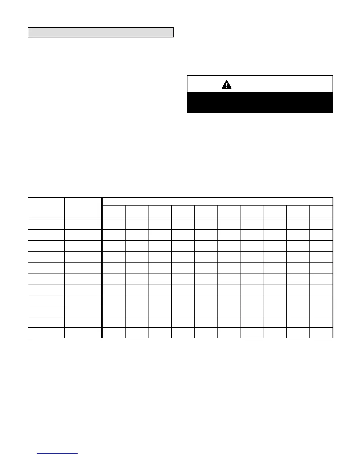
2 - When connecting the gas supply, factors such as
length of run, number of fittings and furnace rating
must be considered to avoid excessive pressure drop.
Table 10 lists recommended pipe sizes for typical apĆ
plications.
3 - The gas piping must not run in or through air ducts,
clothes chutes, gas vents or chimneys, dumb waiters
or elevator shafts.
4 - The piping should be sloped 1/4 inch (6.4 mm) per 15 feet
(4.57 m) upward toward the meter from the furnace. The
piping must be supported at proper intervals [every 8 to
10 feet (2.44 to 3.01 m) using suitable hangers or straps.
A drip leg should be installed in vertical pipe runs to the
unit.
5 - In some localities, codes may require installation of a
manual main shutĆoff valve and union (furnished by
the installer) external to the unit. Union must be of the
ground joint type.
IMPORTANT
Compounds used on threaded joints of gas piping
must be resistant to the actions of liquified petroĆ
leum gases.
NOTE - Install a 1/8 inch NPT plugged tap in the field piping
upstream of the gas supply connection to the unit. The tap
must be accessible for test gauge connection. See figure 16.
NOTE - In case emergency shutoff is required, shut off main
manual gas valve and disconnect main power to unit. These
devices should be properly labeled by the installer.
TABLE 10
GAS PIPE CAPACITY - FT
3
/HR (M
3
/HR)
Nominal Internal
Length of Pipe - feet (m)
Iron Pipe Size
inches (mm)
Diameter
inches (mm)
10
(3.048)
20
(6.096)
30
(9.144)
40
(12.192)
50
(15.240)
60
(18.288)
70
(21.336)
80
(24.384)
90
(27.432)
100
(30.480)
1/4
(6.35)
.364
(9.246)
43
(1.13)
29
(.82)
24
(.68)
20
(.57)
18
(.51)
16
(.45)
15
(.42)
14
(.40)
13
(.37)
12
(.34)
3/8
(9.53)
.493
(12.522)
95
(2.69)
65
(1.84)
52
(1.47)
45
(1.27)
40
(1.13)
36
(1.02)
33
(.73)
31
(.88)
29
(.82)
27
(.76)
1/2
(12.7)
.622
(17.799)
175
(4.96)
120
(3.40)
97
(2.75)
82
(2.32)
73
(2.07)
66
(1.87)
61
(1.73)
57
(1.61)
53
(1.50)
50
(1.42)
3/4
(19.05)
.824
(20.930)
360
(10.19)
250
(7.08)
200
(5.66)
170
(4.81)
151
(4.28)
138
(3.91)
125
(3.54)
118
(3.34)
110
(3.11)
103
(2.92)
1
(25.4)
1.049
(26.645)
680
(919.25)
465
(13.17)
375
(10.62)
320
(9.06)
285
(8.07)
260
(7.36)
240
(6.80)
220
(6.23)
205
(5.80)
195
(5.52)
1-1/4
(31.75)
1.380
(35.052)
1400
(39.64)
950
(26.90)
770
(21.80)
660
(18.69)
580
(16.42)
530
(15.01)
490
(13.87)
460
(13.03)
430
(12.18)
400
(11.33)
1-1/2
(38.1)
1.610
(40.894)
2100
(59.46)
460
(41.34)
1180
(33.41)
990
(28.03)
900
(25.48)
810
(22.94)
750
(21.24)
690
(19.54)
650
(18.41)
620
(17.56)
2
(50.8)
2.067
(52.502)
3950
(111.85)
2750
(77.87)
2200
(62.30)
1900
(53.80)
1680
(47.57)
1520
(43.04)
1400
(39.64)
1300
(36.81)
1220
(34.55)
1150
(32.56)
2-1/2
(63.5)
2.469
(67.713)
6300
(178.39)
4350
(123.17)
3520
(99.67)
3000
(84.95
2650
(75.04)
2400
(67.96)
2250
(63.71)
2050
(58.05)
1950
(55.22)
1850
(52.38)
3
(76.2)
3.068
(77.927)
11000
(311.48)
7700
(218.03)
6250
(176.98)
5300
(150.07)
4750
(134.50)
4300
(121.76)
3900
(110.43)
3700
(104.77)
3450
(97.69)
3250
(92.03)
4
(101.6)
4.026
(102.260)
23000
(651.27)
15800
(447.39)
12800
(362.44)
10900
(308.64)
9700
(274.67)
8800
(249.18)
8100
(229.36)
7500
(212.37)
7200
(203.88)
6700
(189.72)
NOTE-Capacity given in cubic feet (m
3
) of gas per hour and based on 0.60 specific gravity gas.

 Loading...


