Page 24
Turning Off Gas To Unit
1 - Set the thermostat to lowest setting.
2 - Turn off all electrical power to the unit if service is to be
performed.
3 - Remove the access panel.
4 - Turn knob on White Rodgers gas valve 180° either way
to OFF; turn knob on Honeywell valve clockwise
to
OFF. Do not force.
5 - Replace the access panel.
Heating Sequence Of Operation
1 - When the thermostat calls for heat, the combustion air
blower starts after a 5 second delay.
2 - the combustion air pressure switch proves blower opĆ
eration, then energizes the ignition control. The switch
is factoryĆset and requires no adjustment.
3 - After 15-second prepurge cycle, the spark ignitor enĆ
ergizes and the gas valve opens.
4 - The spark ignites the gas, ignition sensor proves the
flame and the combustion process continues.
5 - If flame is not detected after first ignition trial, igniĆ
tion control will repeat steps 3 and 4 four more times
before locking out. To reĆestablish ignition attempts
after lockout, proceed as follows:
a - Turn OFF the power to the furnace.
b - Move the thermostat control from the HEAT" to
the OFF" position.
c - Turn ON the power to the furnace.
d - Move the thermostat control from the OFF" to
HEAT" position.
Gas Pressure Adjustment
Gas Flow
To check for proper gas flow to the combustion chamber,
determine the Btu (kW) input from the unit rating plate. DiĆ
vide this input rating by the Btu (kW) per cubic foot (cubic
meter) of available gas. The result is the required number
of cubic feet (cubic meter) per hour. Determine the flow of
gas through the gas meter for two minutes and multiply by
30 to get the hourly flow of gas.
Gas Pressure
1 - Check the gas line pressure with the unit firing at maxiĆ
mum rate. A minimum of 4.5 in. w.c. for natural gas or
11.0 in. w.c. for LP/propane gas should be maintained.
2 - After the line pressure has been checked and adĆ
justed, check the regulator pressure. See figures 21
and 22 for gas pressure adjustment screw location. For
manifold pressure settings, refer to the rating plate on
the unit. A natural gas to LP/propane gas changeover
kit is required to convert the unit.
High Altitude Information
Refer to the rating plate on the unit for high altitude information.
Other Unit Adjustments
Primary And Secondary Limits
The primary limit is located on the heating compartment vesĆ
tibule panel. Two secondary limits are located in the blower
compartment, behind the blower. These limits are factoryĆset
and require no adjustment.
Flame Rollout Switches (Two)
These manually reset switches are located just above the
burner box. If tripped, a check for adequate combustion air
should be made before resetting.
Combustion Air Pressure Switch
The combustion air pressure switch is located on the heatĆ
ing compartment vestibule panel. This switch checks for
proper combustion air blower operation before allowing
ignition trial. The switch is factory set and requires no adĆ
justment.
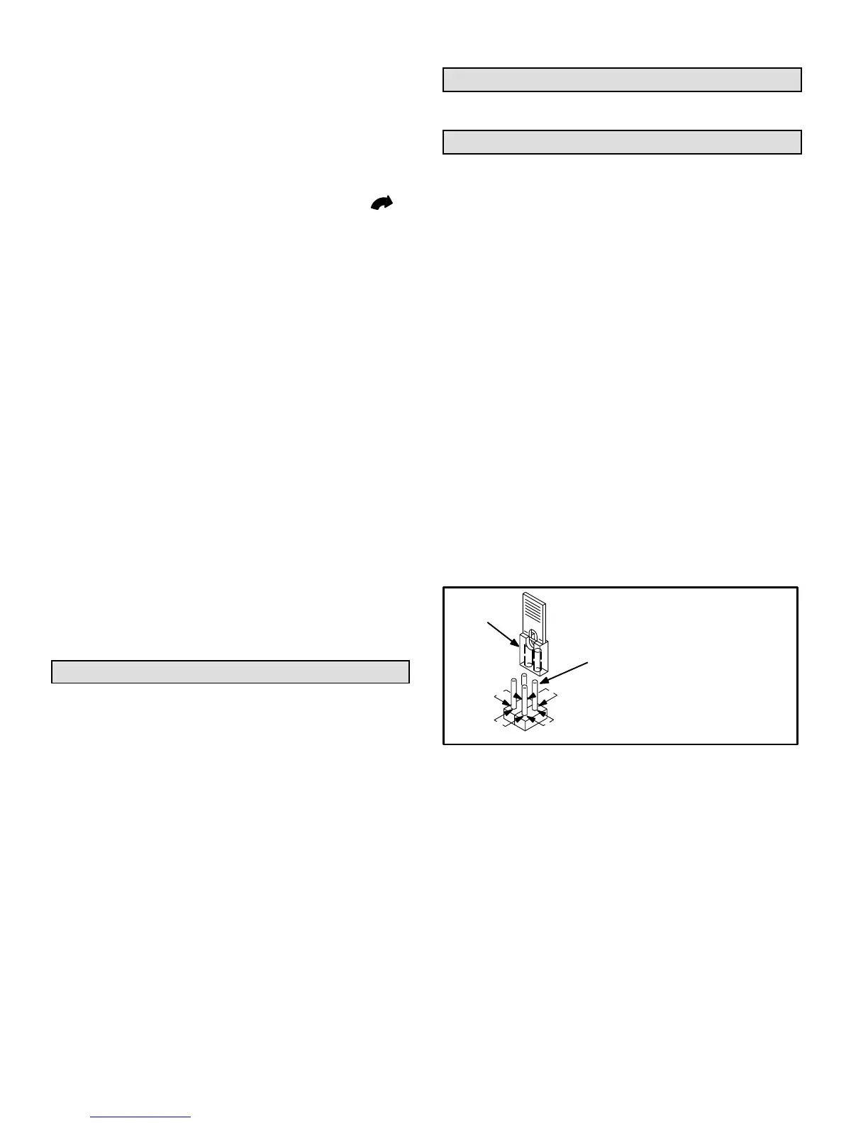
Fan Timer Control
The fan control is part of the integrated control board loĆ
cated on the blower access panel. The fanĆon delay time of
45 seconds is not adjustable. The fanĆoff delay time is facĆ
tory set at 120 seconds and can be adjusted by moving the
jumper on the integrated control board. See figure 23 for
settings.
120
180
90 60
To adjust fan-off delay, remove the
jumper and select the appropriate pin
combination to achieve the desired
delay.
TIMING
JUMPER
TIMING PINS
(seconds)
Fan-off Delay Adjustment
FIGURE 23
Temperature Rise
Check the temperature rise and, if necessary, adjust the
blower speed to maintain the temperature rise within the
range shown on the unit rating plate.
Thermostat Heat Anticipation
Set the thermostat heat anticipation :
0.50 amps White Rodgers gas valves
0.70 amps Honeywell gas valves
Electrical
1 - Check all wiring for loose connections.
2 - Check for the correct voltage at the furnace (furnace
operating).
3 - Check amp-draw on the blower motor.
Motor Nameplate__________Actual__________

 Loading...


