Page 25
Blower Speeds
Note - CFM readings are taken external to unit with a dry
evaporator coil and without accessories.
Note - Units may be equipped with either leaded or leadĆ
less blower motors.
Units with leadless motors -
1 - Turn off the electrical power to furnace.
2 - Remove the two screws holding the fan access panel
in place. Remove the panel.
3 - Grasp the blower motor harness connector located on
the back of the motor. Depress lock tab and pull conĆ
nector from motor.
4 - Refer to blower speed selection chart on unit wiring diaĆ
gram for desired heating or cooling speed.
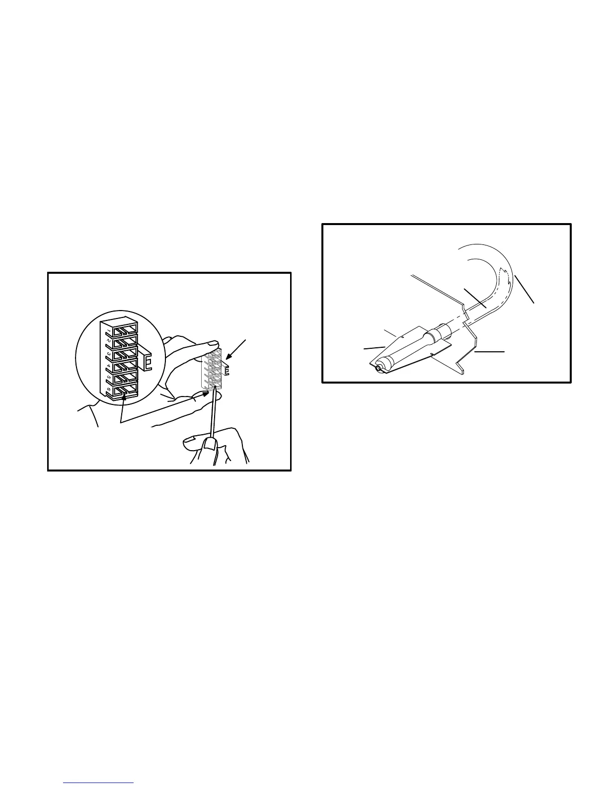
5 - Depress harness connector tab to release wire termiĆ
nal. See figure 24. Select connector location for new
speed. Insert wire terminal until it is securely in place.
Blower Speed Tap Selection
HARNESS
CONNECTOR
DEPRESS TAB TO RELEASE WIRE TERMIĆ
NAL. SELECT CONNECTOR LOCATION
FOR NEW SPEED (REFER TO UNIT WIRĆ
ING DIAGRAM). INSERT WIRE UNTIL IT IS
SECURELY IN PLACE.
LEADLESS MOTORS
FIGURE 24
6 - Reconnect harness at motor.
7 - Resecure fan access panel.
8 - Turn on electrical power to furnace.
Units with leaded motors -
1 - Turn off electrical power to furnace.
2 - Disconnect existing speed tap at control board speed
terminal.
NOTE - TERMINATION OF ANY UNUSED MOTOR
LEADS MUST BE INSULATED.
3 - Refer to blower speed selection chart on unit wiring diaĆ
gram for desired heating or cooling speed.
4 - Connect selected speed tap at control board speed
terminal.
5 - Resecure blower access panel.
6 - Turn on electrical power to furnace.
Flue and Chimney
1 - Check flue pipe, chimney and all connections for tightĆ
ness and to make sure there is no blockage.
2 - Check unit for proper draught.
3 - Is pressure switch closed? Obstructed flue will cause
unit to shut off at pressure switch. Check flue and outĆ
let for blockages.
Burner Flame Adjustment
The G24M burner flame is not adjustable; however, the
flame should be inspected at the beginning of each heating
season. If necessary, clean the burners. Burner flame
should be blue when burning natural gas, blue/yellow when
burning propane gas. See figure 25.
BURNER FLAME
BURNER
FLAME
HEAT
EXCHANGER
TUBE
VEST
PANEL
FLAME APPEARS BLUE IF
BURNING NAT. GAS; BLUE/
YELLOW FOR PROPANE.
FIGURE 25
Turbulator
G24M(X) series units include a ceramic fiber turbulator in
each heat exchanger inlet. The turbulators lower nitrogen
oxide emissions. Prior to unit start-up, inspect the turbulaĆ
tors for shipping damage . The turbulators are fragile; they
should be removed only if it is necessary to replace them.
Failure To Operate
If unit fails to operate check the following:
1 - Is the thermostat calling for heat?
2 - Is the access panel securely in place?
3 - Is the main disconnect switch closed?
4 - Is there a blown fuse or tripped circuit breaker?
5 - Is the filter dirty or plugged? Dirty or plugged filters will
cause the limit control to shut the unit off.
6 - Is gas turned on at the meter?
7 - Is the manual main shut-off valve open?
8 - Is the internal manual shut-off valve open?
9 - Is the unit ignition system in lock out? If unit locks out
again, call the serviceman to inspect the unit for blockĆ
ages.

 Loading...


