Page 26
Service
WARNING
Disconnect power before servicing unit.
CAUTION
Label all wires prior to disconnection when servicing
controls. Wiring errors can cause improper and danĆ
gerous operation. Verify proper operation after serĆ
vicing.
At the beginning of each heating season, the system
should be checked as follows:
Blowers
Check blower wheels for any debris and clean if necessary.
The blower motors are prelubricated for extended bearing
life. No further lubrication is needed.
Filters
All G24M filters are installed external to the unit. Filters
should be inspected monthly.Clean or replace the filters
when necessary to assure proper furnace operation. See
table 11 for filter sizes. Replacement filters for
G24M-45/60/75 units must have a minimum velocity rating
of 400 FPM. Replacement filters for G24M-100/120/140
units require a minimum velocity rating of 625 FPM.
TABLE 11
Model Number Filter Size - inches (mm)
G24M-45/60/75 16 X 20 X 1 (406 X 508 X 25)
G24M-100/120/140 20 X 20 X 1 (508 X 508 X 25)
WARNING
The blower access panel must be securely in place
when the blower and burners are operating. Gas
fumes, which could contain carbon monoxide, can
be drawn into living space resulting in personal injuĆ
ry or death.
Flue And Chimney
Check the flue pipe, chimney and all connections for tightĆ
ness and to make sure there is no blockage.
Burners
Inspect the burners and burner flame at the beginning of
each heating season. If necessary, clean the burners as
indicated below:
1 - Turn off electrical and gas supply to unit.
2 - Disconnect gas supply piping and remove gas manĆ
ifold.
3 - Disconnect ignitor and flame sensor leads.
4 - Remove burner tray and burners.
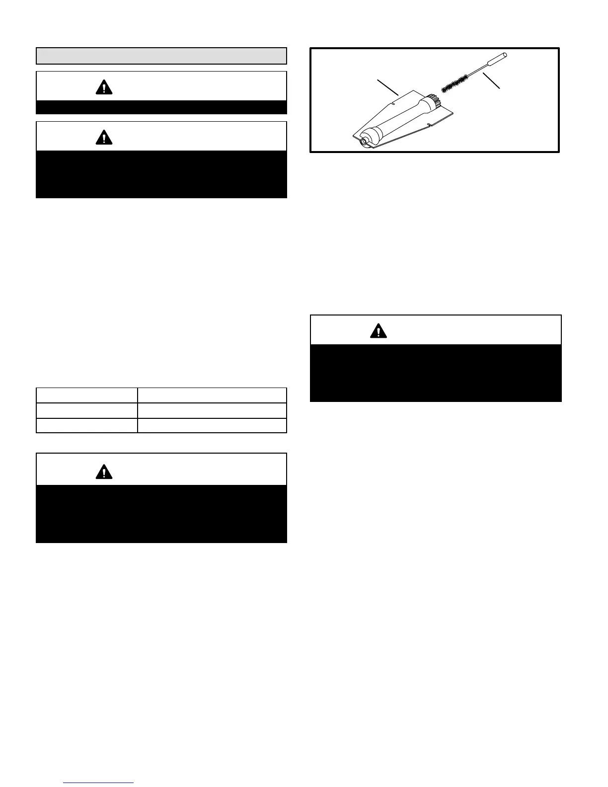
5 - Clean the inside of each burner with a bottle brush as
shown figure 26.
Cleaning Burners
BOTTLE
BRUSH
BURNER
FIGURE 26
6 - Replace burners and burner tray, making sure burners
are properly seated in slots on tray and orifice in manĆ
ifold.
7 - Check electrode gap using appropriately sized twist
drills or feeler gauges. Gap should be between 0.110
and 0.140 inches (2.79 to 3.56mm).
8 - Reinstall burner box and gas supply piping. ReconĆ
nect ignitor and flame sensor leads.
9 - Carefully check all piping connections (factory and field)
for gas leaks. Use a leak detecting solution or other preĆ
ferred means.
IMPORTANT
Some soaps used for leak detection are corrosive to
certain metals. Carefully rinse piping thoroughly afĆ
ter leak test has been completed. Do not use
matches, candles, flame or other sources of ignition
to check for gas leaks.
10 - Restore electrical power and gas supply. Follow lightĆ
ing instructions on front of unit. Check burner flame
and adjust if necessary.
Heat Exchanger
Periodically inspect the heat exchanger tubes and the flue
box for corrosion. If necessary, clean as indicated below:
1 - Turn off the electrical power and gas supply to the furĆ
nace.
2 - Disconnect the wiring to the combustion air fan.
3 - Remove the screws securing the flue box to the furĆ
nace. Clean the flue box with a wire brush (brassĆ
bristle brush recommended).
4 - Disconnect the gas supply piping and the ignitor and
sensor wires. Remove the burner assembly from the
furnace.
5 - Pull a largeĆbore wire brush (brassĆbristle brush recomĆ
mended) through each heat exchanger tube to clean.
6 - Reinstall the flue box using a new gasket.
7 - Reconnect the combustion air fan wiring.
8 - Reinstall the burner box, ignitor and sensor wires and
the gas supply piping.
9 - Carefully check all piping connections (factory and field)
for gas leaks. Use a leak detecting solution or other preĆ
ferred means.

 Loading...


