Page 48
2
3
5
6
4
1
7 8
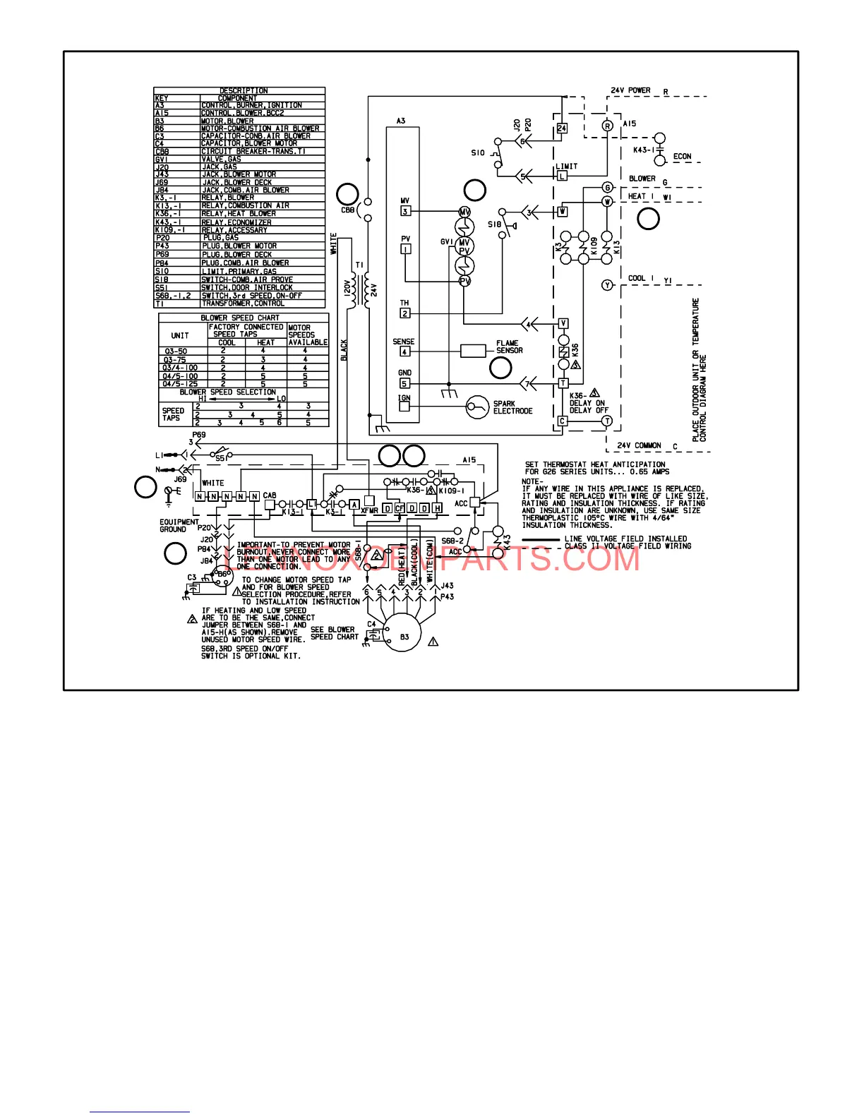
E- G26 -1 and -2 Models
1Ć When disconnect is closed, 120V is routed through
door interlock switch (S51) to feed the line voltage
side of the blower control (A3) and transformer T1 priĆ
mary. Door interlock switch must be closed for A3 and
T1 to receive voltage.
2Ć T1 supplies 24VAC to terminal 24VAC" on A3. In turn,
terminal R" of A3 supplies 24VAC to terminal RC" of
the indoor thermostat (not shown).
3Ć When there is a call for heat, W1 of the thermostat enĆ
ergizes W of the furnace control with 24VAC.
4Ć CAB of the blower control energizes the combustion
air blower (B6). When the combustion air blower nears
full speed, combustion air prove switch (S18) closes.
5Ć When S18 closes, assuming primary limit (S10) is
closed, the ignition control opens the pilot valve and
begins spark.
6Ć When flame is sensed, spark stops and main valve
opens to light main burners.
7Ć After 45 seconds, blower control (A3) energizes the inĆ
door blower.
8Ć When heat demand is satisfied, W1 of the thermostat
deĆenergizes W of the furnace control and the furnace
control immediately deĆenergizes the gas valve. The
combustion air blower immediately stops. Also, the inĆ
door blower runs for a designated period (90-330 secĆ
onds) as set by jumper on blower control.

 Loading...


