Page 12
TABLE 3
SureLight BOARD J156 (J2) TERMINAL
DESIGNATIONS
PIN # FUNCTION
1 Ignitor
2
Not Used
3
Ignitor Neutral
4
Combustion Air Blower Line Voltage
5
Not Used
6
Combustion Air Blower Neutral
TABLE 4
SureLight BOARD J58 (J1) TERMINAL
DESIGNATIONS
PIN # FUNCTION
1 Primary Limit In
2
Gas Valve Common
3
Roll Out Switch Out
4
Gas Valve 24V
5
Pressure Switch In
6
Pressure Switch and Primary Limit Out
7
Not Used
8
Roll Out Switch In
9
Ground
CAUTION
Electrostatic discharge can affect electronic
components. Take precautions during furnace
installation and service to protect the furnace's
electronic controls. Precautions will help to
avoid control exposure to electrostatic disĆ
charge by putting the furnace, the control and
the technician at the same electrostatic potenĆ
tial. Neutralize electrostatic charge by touching
hand and all tools on an unpainted unit surface,
such as the gas valve or blower deck, before perĆ
forming any service procedure.
ELECTROSTATIC DISCHARGE (ESD)
Precautions and Procedures
a-Electronic Ignition
On a call for heat the SureLight control monitors the comĆ
bustion air blower pressure switch. The control will not beĆ
gin the heating cycle if the pressure switch is closed (by-
passed). Once the pressure switch is determined to be
open, the combustion air blower is energized. When the
differential in the pressure switch is great enough, the
pressure switch closes and a 15-second pre-purge beĆ
gins. If the pressure switch is not proven within 2-1/2 minĆ
utes, the control goes into Watchguard-Pressure Switch
mode for a 5-minute re-set period.
After the 15-second pre-purge period, the SureLight igniĆ
tor warms up for 20 seconds after which the gas valve
opens for a 4-second trial for ignition. G26 units with board
63K89, 24L85 or 56L83: the ignitor stays energized for the
first second of the 4-second trial. Units with board 97L48:
ignitor stays energized for the full 4-second ignition trial. If
ignition is not proved during the 4-second period, the conĆ
trol will try four more times with an inter purge and warm-up
time between trials of 35 seconds. After a total of five trials
for ignition (including the initial trial), the control goes into
Watchguard-Flame Failure mode. After a 60-minute reset
period, the control will begin the ignition sequence again.
The SureLight control board has an added feature that
prolongs the life of the ignitor. After a successful ignition,
the SureLight control utilizes less power to energize the igĆ
nitor on successive calls for heat. The control continues to
ramp down the voltage to the ignitor until it finds the lowest
amount of power that will provide a successful ignition.
This amount of power is used for 255 cycles. On the 256th
call for heat, the control will again ramp down until the lowĆ
est power is determined and the cycle begins again.
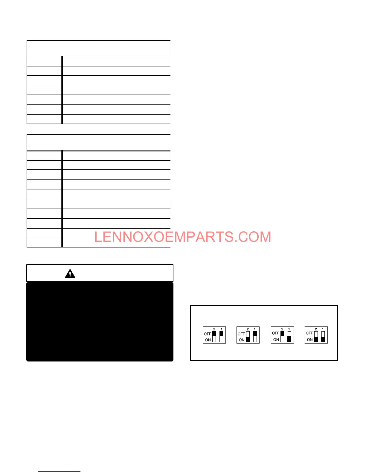
b-Fan Time Control
The fan on time of 45 seconds is not adjustable. Fan off
time (time that the blower operates after the heat demand
has been satisfied) can be adjusted by flipping the dip
switches located on the SureLight integrated control. The
unit is shipped with a factory fan off setting of 90 seconds.
Fan off time will affect comfort and is adjustable to satisfy
individual applications. See figure 12.
FIGURE 12
FANĆOFF TIME ADJUSTMENT
To adjust fan-off timing, flip dip switch to desired setting.
60sec. 90sec. 120sec. 180sec.
7-Blower Motors and Capacitors
All G26 units use direct drive blower motors. All motors
used are 120V permanent split capacitor motors to ensure
maximum efficiency. See table 5 for ratings.
 Loading...

