Page 23
When horizontally vented, minimum clearance for
termination from electric meters, gas meters, regulaĆ
tors and relief equipment is 4 ft. (1.2m) for US installaĆ
tions. Refer to the current CAN/CGA-B149.1 and .2
for installations in Canada or with authorities having
local jurisdiction.
At vent termination, care must be taken to maintain
protective coatings over building materials (proĆ
longed exposure to exhaust condensate can destroy
protective coatings). It is recommended that the exĆ
haust outlet not be located within 6 feet (1.8m) of a
condensing unit because the condensate can damĆ
age the painted coating.
IMPORTANT
Combustion air intake inlet and exhaust outlet
should not be located within 6 ft. (1.8m) of dryer vent
or combustion air inlet or outlet of another apĆ
pliance. Piping should not exit less than 3 ft. (.91m)
from opening into another building.
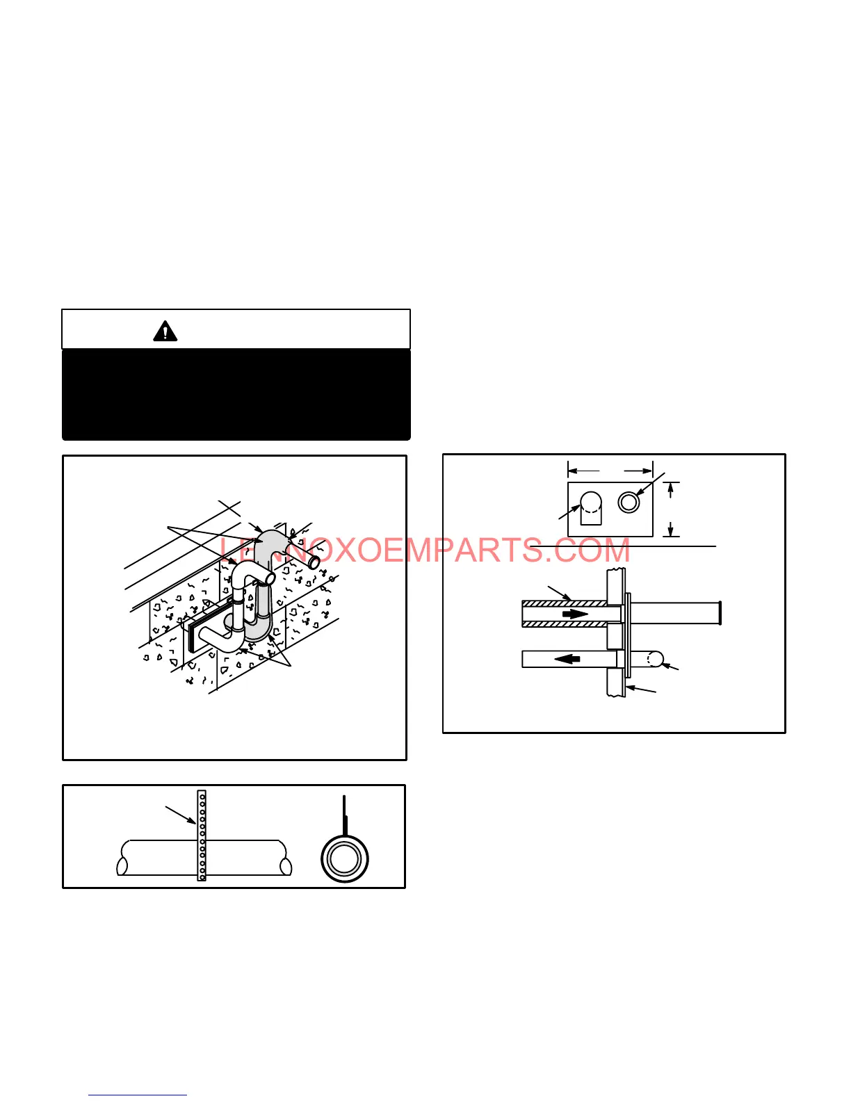
FIGURE 32
Inches (mm)
FRONT VIEW
WALL TERMINATION
(22G44) LB-49107CD for 2(51) Venting
(44J40) LB-65701A for 3(76) Venting
3 (76) OR
2 (51) 90 ELBOW
1/2 (13)
FOAM
INSULATION
Inches(mm)
3 (76) OR
2 (51) 90 ELBOW
3 x 2 (76 x 51) OR
2 x 1-1/2 (51 x 38)
REDUCER BUSHING LOCAĆ
TION
FOR OFFSET TERMINATION
Optional TurnĆ
down
(Not Shown)
May Be Used on
Intake Only
FIGURE 33
METAL OR PLASTIC
STRAPĆ
PING
OR LARGE
WIRE TIES
10- Suspend piping using hangers at a minimum of every
5 feet (1.52m) for schedule 40 PVC and every 3 feet
(.91m) for ABS-DWV, PVC-DWV, SPR-21 PVC, and
SDR-26 PVC piping. A suitable hanger can be fabriĆ
cated by using metal or plastic strapping or a large
wire tie.
11- In areas where piping penetrates joists or interior
walls, hole must be large enough to allow clearance
on all sides of pipe through center of hole using a
hanger.
12- Isolate piping at the point where it exits the outside
wall or roof.
13- When furnace is installed in a residence where unit is
shut down for an extended period of time, such as a
vacation home, make provisions for draining condenĆ
sate collection trap and lines.
14- Based on the recommendation of the manufacturer, a
multiple furnace installation may use a group of up to
four termination kits WTK assembled together horizonĆ
tally, as shown in figure 35.
FIGURE 34
12
(305)
5
(127)
1/2 (13) Foam
Insulation in
Unconditioned Space
EXHAUST VENT
INTAKE VENT
OUTSIDE WALL
EXHAUST VENT
INTAKE
VENT
Front View
Side View
VENT TERMINATIONS
WALL TERMINATION KIT (30G28) WTK
Inches (mm)
 Loading...


