Page 19
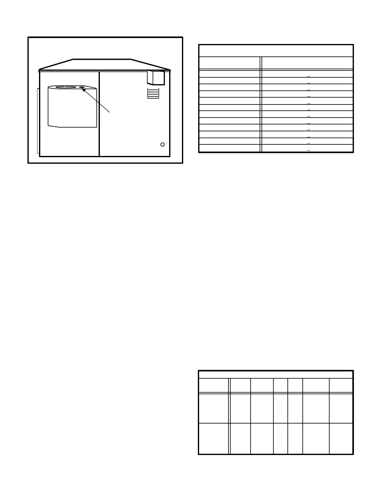
FIGURE 14
SECONDARY LIMIT
GCS16-410-100 AND GCS16R-411-100 ONLY
BLOWER
SECONDARY LIMIT
LOCATION
6-Flame Rollout Switch S47
Flame rollout switch S47 is a high temperature limit lo
cated just above the burner air intake opening in the burn
er enclosure (see figure 12). The limit is a N.C. SPST re
settable limit connected in series with ignition control A3.
When S47 senses flame rollout, the ignition control imme
diately stops ignition and closes the gas valve. The switch
is factory set and cannot be adjusted.
Initially, only units equipped with a burner enclosure were
equipped with rollout switch S47 (see section 3- Burner
Enclosure and figure 12). In November 1989, rollout
switch was added to all units. It is an A.G.A. mandated re
quirement on all gas furnaces produced after that date. In
all 75,000, 100,000 and 125,000 Btuh heat exchanger
units produced after November 1989, the switch is
installed in a burner enclosure as shown in figure 12. In all
50,000 Btuh heat exchanger units produced after Novem
ber 1989, the switch is installed as shown in figure 8.
7-Combustion Air Prove Switch S18
The combustion air prove switch (S18) is a SPST N.O. dif
ferential pressure switch used to monitor combustion air
blower operation. A flexible hose connects one side of the
switch to the blower housing. The other side of the switch
is open to the atmosphere. The switch is wired in series
with ignition control A3. Prove switch S18 closes when the
combustion air blower reaches full speed to allow the igni
tion control to energize. This proves that the combustion
air blower is operating and allows the heating cycle to con
tinue.
The combustion air prove switch is factory set and is not
adjustable. Factory settings are shown in Table 3.
COMBUSTION AIR PROVE SWITCH
FACTORY SETTING
TABLE 3
Unit
inches w.c.
N.O., closes on pressure drop
GCS16H-261
GCS16H-311
0.45 + 0.05
0.65 + 0.05
GCS16-411/413-100 0.45 + 0.05
GCS16-511/513-125 0.90 + 0.05
GCS16-651/653-75
GCS16R-650-125
0.45 + 0.05
0.90 + 0.05
GCS16R-411-100 0.65 + 0.05
GCS16-411/413-50 0.45 + 0.05
GCS16R-411-50 0.45 + 0.05
GCS16R-651-75 0.45 + 0.05
GCS16R-511-125 0.90 + 0.05
GCS16-651/653-125 0.90 + 0.05
8-Combustion Air Blower B6
Combustion air blower B6 provides fresh air to the burner
while clearing the combustion chamber of exhaust gases.
The blower begins operating immediately upon receiving
a thermostat demand and is deenergized immediately
when thermostat demand is satisfied.
Blowers on 50K, 75K and 100K Btuh heat exchangers are
manufactured by Lennox and can be disassembled for
cleaning. Blowers on 125K Btuh heat exchangers are fac
tory assembled as a unit and cannot be disassembled for
cleaning.
Combustion air blower specifications are shown in table 4.
All combustion air blower motors are sealed and cannot be
oiled.
The tube connecting the switch to the blower flue box must
be sloped in a manner that will prevent condensate from
collecting in the tube. It is normal for a small amount of
condensate to form in the tube during unit operation. The
tube and switch must be allowed to drain accumulated
condensate between thermostat demands. If the tube is
positioned so that accumulated condensate is trapped in
the tube, the unit may run improperly or may lock out.
TABLE 4
COMBUSTION AIR BLOWER
Unit Input
Btuh
Type HP RPM
Volts/
phase
Bearings Misc.
50K
75K
100K
125K
208/
230/1
Shaded
Pole
1-1/2
Stack
1/25 3200 Ball
Requires
T3 when
used in
460/575
volt units
208/
230/1
Requires
T3 when
used in
460/575
volt units
Ball32001/10PSC
 Loading...