Page 16
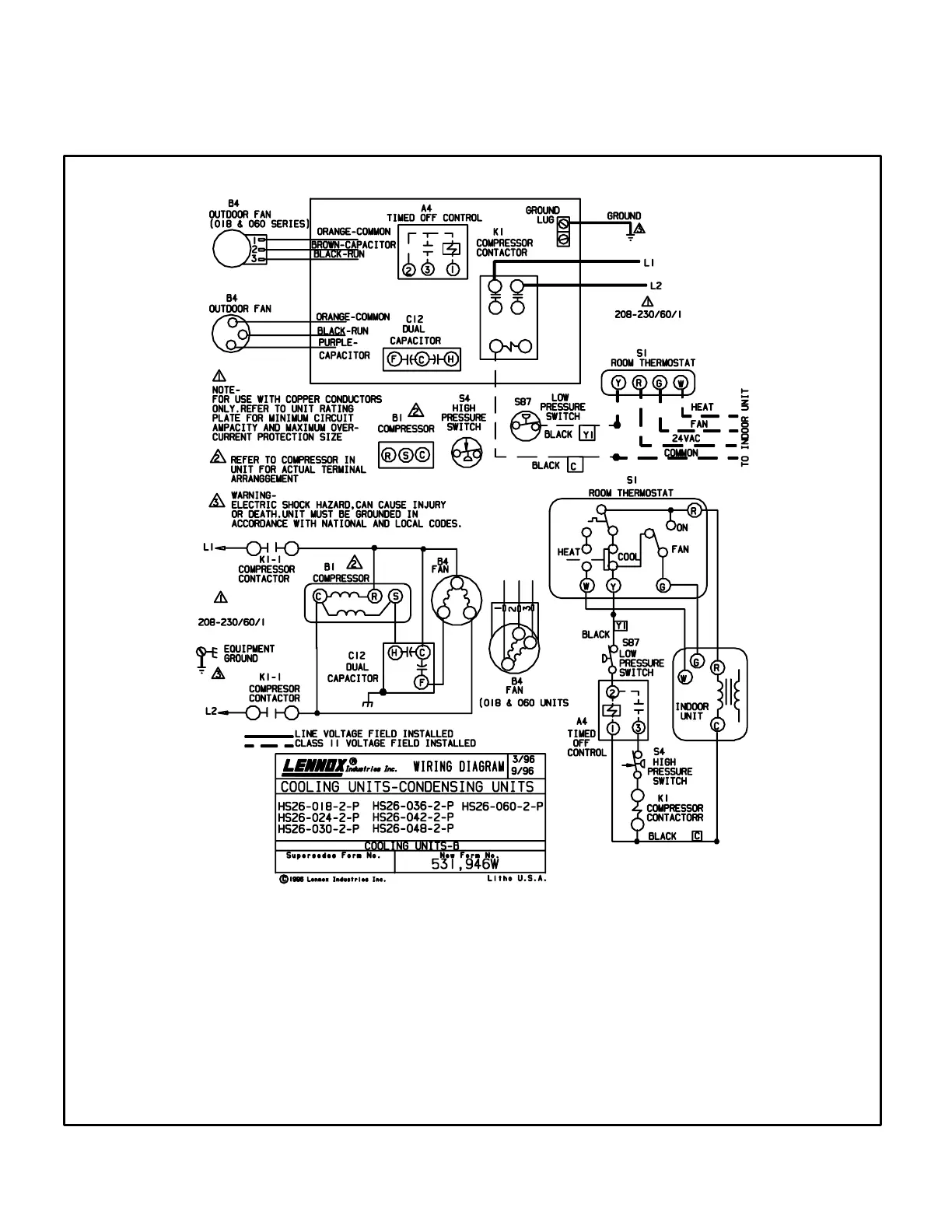
B−Unit Diagram HS26−018/060−2P (Late Models)
Operation Sequence
1− Cooling demand energizes thermostat terminal Y. Voltage from terminal Y passes through low pressure
switch and the timed off control (TOC), which energizes K1 compressor contactor coil (provided 5 minute
delay is satisfied).
2− K1−1 and K1−2 contacts close energizing B1 compressor and B4 outdoor fan.
3− When cooling demand is satisfied, K1−1 and K1−2 contacts open de−energizing compressor and outdoor fan.
Timed off control begins 5 minute off time.




 To Next Page