EasyManua.ls Logo

Lennox HS26-024

Lennox HS26-024
18 pages
To Next Page IconTo Next Page
Loading...
SERVICE
HS26
UNIT
INFORMATION
Page 1
1996 Lennox Industries Inc.
Corp. 9622−L12
Litho U.S.A.
EARLY/LATE
MODEL SERIES
Revised 04−2002
HS26 SERIES UNITS
The HS26 is a high efficiency residential split−system con
densing unit which features a scroll compressor. Early
model HS26 units (−261,−311,−411, and −461) are available
in sizes ranging from 2 through 3−1/2 tons. Late model
HS26 units (−018, −024, −030, −036, −042, −048 and −060)
are available in sizes ranging from 1−1/2 through 5 tons.
The series is designed for use with an expansion valve in
the indoor unit.This manual is divided into sections which
discuss the major components, refrigerant system, charg
ing procedure, maintenance and operation sequence. In
formation in this manual covers both early and late model
HS26 units.
All specifications in this manual are subject to change.
Late Model
HS26 shown
ELECTRICAL DATA (Early Model)
SPECIFICATIONS (Early Model)
Model No. HS26−261 HS26−311 HS26−411 HS26−461
Outdoor
Coil
Condenser
Fan
HCFC−22 (charge furnished)
Face area (sq.ft.)
Tube diameter (in.)
No. of Rows
Fins per inch
Diameter (in.)
No. of Blades
Motor hp
Cfm
RPM
Watts
Liquid line connection
Suction line connection
HS26−261 HS26−311 HS26−411 HS26−461
Model No.
Line voltage data − 60hz./1 phase
Compressor
Rated load amps
Power factor
Locked rotor amps
Condenser
Fan Motor
Full load amps
Locked rotor amps
Max fuse or c.b. size (amps)
*Minimum circuit ampacity
outer / inner
*Refer to National Electrical Code Manual to determine wire, fuse and disconnect size requirements.
NOTE − Extremes of operating range are plus 10% and minus 5% of line voltage
11.8/5.4 15.9/5.5 15.9/15.3 21.6/20.8
3/8 3/8 3/8 3/8
1.36 1.36 2.0 2.0
20 20 20 20
24 24 24 24
3333
1/6 1/6 1/6 1/6
3150 3150 3000 3230
820 820 820 820
210 210 230 205
7lbs. 11oz. 8lbs. 1oz. 9lbs. 0oz. 11lbs. 3oz.
3/8 3/8 3/8 3/8
3/4 3/4 3/4 11/8
208/230V 208/230V 208/230V 208/230V
11.6 13.5 18.0 20
.96 .96 .96 .97
62.5 76.0 90.5 107
1.1 1.1 1.1 1.1
2.0 2.0 2.0 2.0
25 30 40 45
15.6 18.0 23.6 26.1
*Refrigerant charge sufficient for 25 ft. (7.6 m) length of refrigerant lines.
Question and Answer IconNeed help?

Do you have a question about the Lennox HS26-024 and is the answer not in the manual?

Lennox HS26-024 Specifications

General IconGeneral
ModelHS26-024
TypeSplit System Air Conditioner
RefrigerantR-410A
Tons2
Operating Voltage208/230V
Phase1
Cooling Capacity24, 000 BTU/h
SEER Rating16
Compressor TypeSingle Stage
Sound Level (Indoor)Not Available
Unit Weight (Indoor)Not Available
Dimensions (Indoor)Not Available

Summary

HS26 Series Units Introduction

Early Model Specifications

Technical specifications for early HS26 models, including physical and performance data.

Early Model Electrical Data

Electrical characteristics and ratings for early HS26 models.

HS26 Late Model Specifications

Late Model Specifications

Technical specifications for late HS26 models, covering physical and performance details.

Late Model Electrical Data

Electrical characteristics and ratings for late HS26 models.

Scroll Compressor Functionality

Scroll Compressor Working Principle

Explains the gas intake, compression, and discharge process of scroll compressors.

Unit Components and Safety

Electrical Safety Precautions

Critical warnings about electrical shock, ESD, and power disconnection.

Service Valve Procedures (Early Models)

Liquid Line Service Valve Access

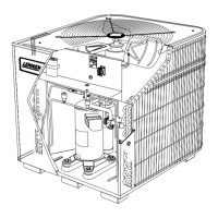
Step-by-step guide to accessing and using the liquid line service valve.

Suction Line Service Valve Access

Step-by-step guide to accessing and using the suction line service valve.

Refrigerant Charging and Testing

System Charging Guidelines

Overview of factory charge and adjustments for line set length.

System Evacuation and Pressure Tables

Evacuation Procedure Steps

Detailed steps for evacuating the system to remove non-condensables.

Charging Methods and Approach

Early Model Wiring Diagrams

Late Model Wiring Diagrams (2 P)

Late Model Wiring Diagrams (3&4 P)

Late Model Wiring Diagrams (3-Phase)

Related product manuals