EasyManua.ls Logo

Lennox KCC092S4

Lennox KCC092S4
51 pages
To Next Page IconTo Next Page
To Previous Page IconTo Previous Page
Loading...
Page 16
I-UNIT COMPONENTS





ELECTROSTATIC DISCHARGE (ESD)
Precautions and Procedures
CAUTION
   󰀨
electronic components. Take precautions
to neutralize electrostatic charge by
touching your hand and tools to metal
prior to handling the control.

        

pressor compartment.
1-Disconnect Switch S48
All units may be equipped with an optional disconnect
switch S48 or circuit breaker CB10. S48 and CB10 are

cian to disconnect power to the unit.
2-Control Transformer T1


   




BLUE YELLOW
ORANGE
RED
BLACK
230 VOLTS
208 VOLTS
PRIMARY
SECONDARY
208/230V TRANSFORMER
FIGURE 3
3-Terminal Strip TB1
All indoor thermostat connections are made at terminal
        

         
place.
4-Condenser Fan Capacitors C1 & C2



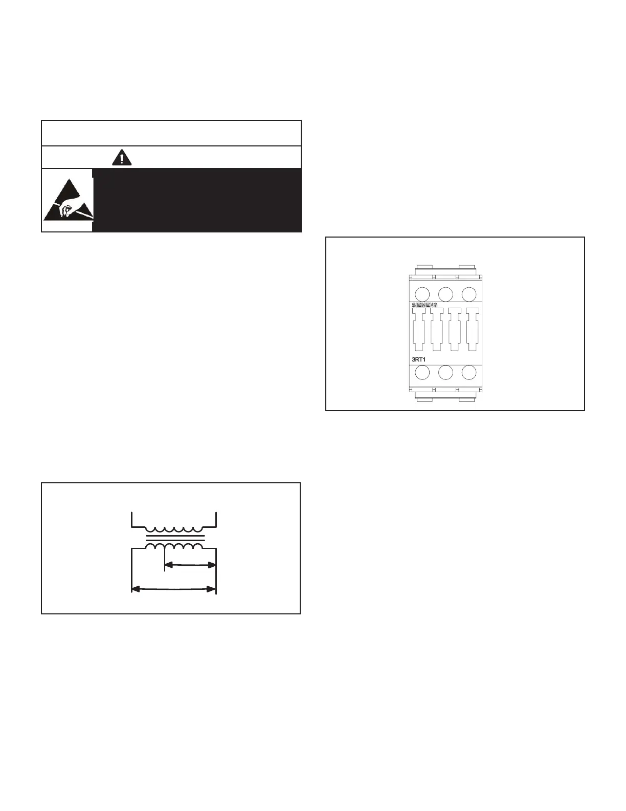
5-Compressor Contactor K1 & K2
    
         
K2 energize compressors B1 and B2 in response to

CONTACTOR
FIGURE 4
6-Blower Contactor K3


the indoor blower motor B3 in response to blower de
mand. K3 is energized by a thermostat cooling demand.

7-Condenser Fan Relay K10




          





Related product manuals