Page 29
2 - No Economizer Installed in Unit -
See table 8 for cooling operation.
combination of thermostat demands will
energize the economizer. See TABLE 9
cooling operation.
TABLE 8
COOLING OPERATION - NO ECONOMIZER
T’Stat Compressors OD Fans
Compr. 1 Low Both On
Compr. 1 Low; Compr. 2 On Both On
Compr. 1 High; Compr. 2 On Both On
TABLE 9
COOLING OPERATION - WITH ECONOMIZER
T’Stat Compressors OD Fans
Compr. 1 Low Both On
Compr. 1 High Both On
3 - Units contain two refrigerant circuits or stages. See
4 - Each refrigerant circuit is separately charged with
amount of charge.
for proper method to check refrigerant charge
Three Phase Scroll Compressor Voltage Phasing
Three phase scroll compressors must be phased
sequentially to ensure correct compressor and blower
rotation and operation. Compressor and blower are wired
in phase at the factory. Power wires are color-coded as
1 - Observe suction and discharge pressures and
blower rotation on unit start-up
is not correct:
2 -
marking.
3 - Disconnect all remote electrical power supplies.
4 -
Do not reverse wires at
.
Make sure the connections are tight.
Discharge and suction pressures should operate at their
normal start-up ranges.
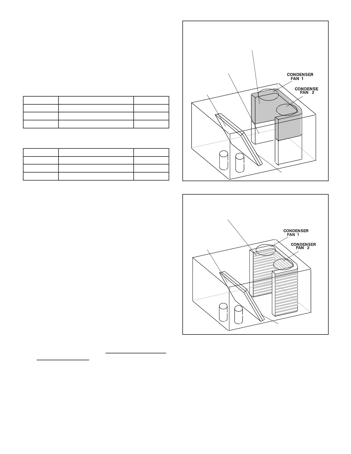
REFRIGERANT STAGES - 092, 102, 120, 150
1
2
(BOTH FANS ARE ENERGIZED
WITH A Y1 DEMAND)
CONDENSER COIL
KG/KC 092, 102 - Stage 2
KG/KC 120, 150 - Stage 1
EVAPORATOR
COIL STAGE 1
CONDENSER COIL
KG/KC 092, 102 - Stage 1
KG/KC 120, 150 - Stage 2
EVAPORATOR
COIL STAGE 2
FIGURE 20
TUBE/FIN OD COIL
1
2
(BOTH FANS ARE ENERGIZED
WITH A Y1 DEMAND)
CONDENSER COIL
STAGES 1 & 2
EVAPORATOR
COIL STAGE 1
EVAPORATOR
COIL STAGE 2
FIGURE 21
 Loading...

