Page 20
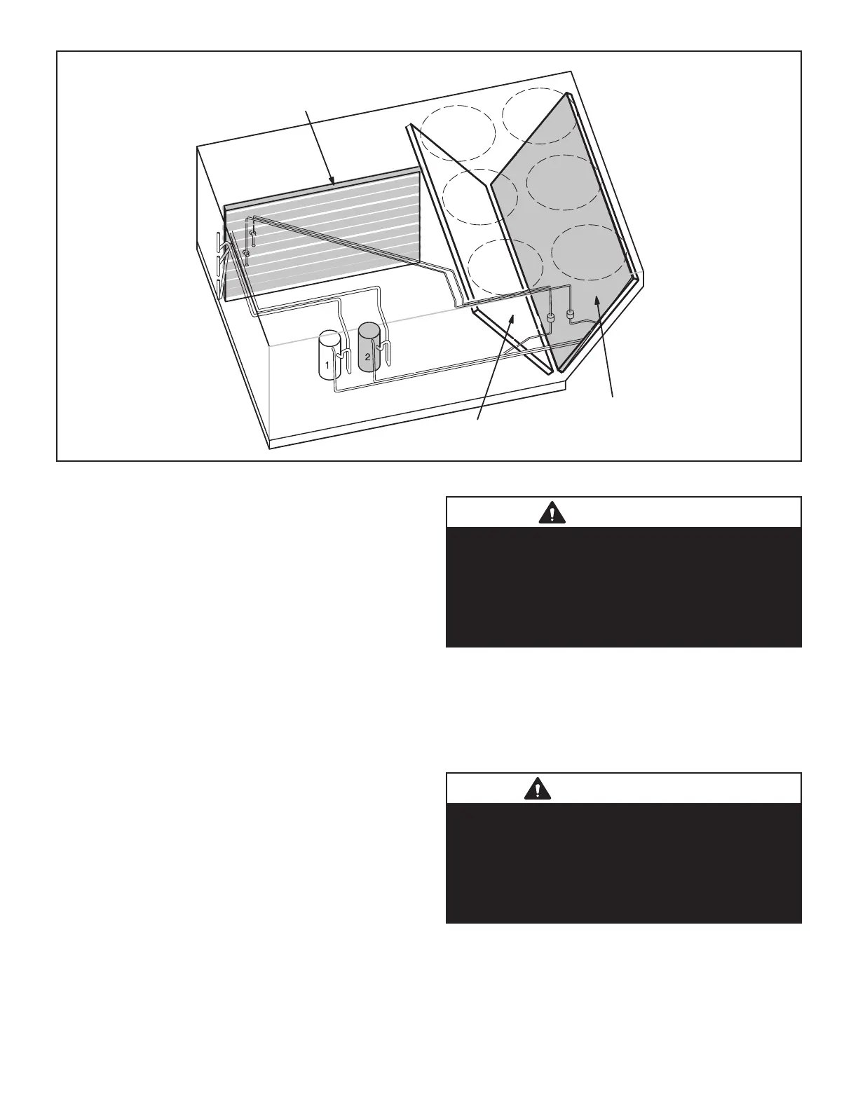
REFRIGERANT CIRCUITS
CIRUIT 2
OUTDOOR COIL
CIRCUIT 1
OUTDOOR COIL
INDOOR COIL CIRCUIT 1 & 2
ARE INTERLACED
FIGURE 8
B-Cooling Components
Units use independent cooling circuits consisting of one
per circuit.
-
stalled economizer. All units intertwined evaporators.
pressure switch and low pressure switch.
1-Compressors B1 and B2
All units use scroll compressors. All units use 2 compres-
-
-
of each compressor is added to reach the total capacity
of the unit. See “SPECIFICATIONS” and “ELECTRICAL
DATA” (table of contents) or compressor nameplate for
WARNING
Electrical shock hazard. Compressor must be
grounded. Do not operate without protective cover
over terminals. Disconnect power before removing
protective cover. Discharge capacitors before
servicing unit. Failure to follow these precautions
could cause electrical shock resulting in injury or
death.
Each compressor is energized by a corresponding com-
pressor contactor.
NOTE-Refer to the wiring diagram section for specic unit
operation.
IMPORTANT
Some scroll compressors have an internal vacuum
protector that will unload scrolls when suction
pressure goes below 20 psig. A hissing sound
will be heard when the compressor is running
unloaded. Protector will reset when low pressure
in system rises above 40 psig. DO NOT REPLACE
COMPRESSOR.
 Loading...


