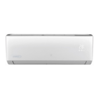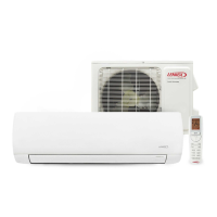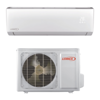
Do you have a question about the Lennox LI018CI-180P432 and is the answer not in the manual?
| Cooling Capacity | 18, 000 BTU/h |
|---|---|
| Voltage | 208/230V |
| Phase | 1 |
| Refrigerant | R-410A |
| Sound Level (Outdoor Unit) | 52 dB(A) |
Safety measures and warnings before performing maintenance on the unit.
List of error codes and their corresponding malfunctions for troubleshooting.
Diagnostic steps for identifying and resolving primary malfunctions.
Guide for resolving common operational issues and non-critical faults.
Exploded view and list of parts for the indoor unit.
Exploded view and list of parts for the outdoor unit.
Step-by-step guide for disassembling and removing indoor unit components.
Step-by-step guide for disassembling and removing outdoor unit components.
Detailed technical specifications of the air conditioning units.
Graphs illustrating unit performance curves under various conditions.
Data on how cooling/heating capacity changes with ambient temperature.
Information on sound pressure and power levels at different operating speeds.
Performance data tables for cooling and heating modes.
Dimensional drawings and specifications for the indoor unit.
Dimensional drawings and specifications for the outdoor unit.
Electrical wiring schematics for indoor and outdoor units.
Layouts of the printed circuit boards for unit components.
Explanation of remote controller buttons, display icons, and basic operation.
Detailed explanation of operating modes and special functions of the unit.
Critical safety warnings and general precautions before installation and maintenance.
Specific safety guidelines for electrical work during installation and maintenance.
Safety measures and procedures for physically installing the unit.
Safety guidelines and warnings for handling refrigerants.
Diagrams showing required clearances and dimensions for unit installation.
Checklist of parts required for installation.
Guidance on choosing optimal locations for indoor and outdoor units.
Standards and safety requirements for electrical connections.
Step-by-step instructions for installing the indoor unit.
Step-by-step instructions for installing the outdoor unit.
Procedures for vacuum pumping and leak testing the refrigerant system.
Final checks and operational testing after installation completion.
Safety warnings and procedures before performing maintenance.
List of error codes and their meanings for troubleshooting.
Diagnostic steps for major malfunctions.
Guide for resolving common operational issues.
Indoor unit components breakdown and corresponding part numbers.
Outdoor unit components breakdown and corresponding part numbers.
Step-by-step guide for disassembling the indoor unit.
Step-by-step guide for disassembling the outdoor unit.
Conditions and temperature settings for cooling operation.
Conditions and temperature settings for dehumidifying operation.
Operation status of components in air-supplying mode.
Conditions and temperature settings for heating operation.
Conditions for starting and finishing defrosting operations.
Logic for compressor, fan, and 4-way valve control.
Handles starting, frequency, power-off, and continuous fault conditions for frozen-prevention.
Handles starting, frequency, power-off, and continuous faults for cooling overload.
Starting estimation for heating overload protection.
Handles starting, frequency, power-off, and continuous faults for discharge temp protection.
Handles frequency, power-off, and continuous faults for overcurrent.
Reducing frequency and stopping for heating overload.
Reducing frequency and power turn-off for heating overload.
Compressor power turn-off during heating overload.
Handling continuous heating overload power turn-off.
Initial checks for discharge temperature protection.
Limiting frequency based on discharge temperature.
Reducing frequency and stopping for discharge temp protection.
Reducing frequency and power turn-off for discharge temp protection.
Compressor power turn-off due to discharge temperature.
Handling continuous discharge temp power turn-off.
Limiting frequency based on overcurrent.
Reducing frequency due to overcurrent.
Compressor power turn-off due to overcurrent.
Handling continuous overcurrent power turn-off.
