Page 31
High Pressure Switch S4
S4 is a N.C. auto-reset high pressure switch located on
the discharge line. The switch shuts o the compressor
when discharge pressure rises above the factory setting.
The switch on LRP14/16 series units is set to open at 590
+ 10 psi and close at 418 + 10 psi. S4 is not adjustable.
Float Switch
A oat switch is included with the downow kit or can be
ordered as an accessory (oat switch is factory installed
on the LRP16 series). The oat switch is designed to pre-
vent condensate water from overowing the condensate
pan due to a restriction in the condensate drain line. The
oat switch is eld-installed in the condensate drain pan
near the drain exit (oat switch is factory installed on the
LRP16 series). Refer to the installation instruction for the
oat switch kit or the downow kit for location and cutting
of the red wire located in the blower compartment.
ELECTRIC HEAT
Matchups and Ratings
Matchups and ratings are listed with “ELECTRICAL
DATA”.
Electric Heat Components
See gure 12 for electric heat parts arrangement.
Limit Switches 1, 2, 3 and 4
Limit switches 1, 2, 3 and 4 are N.C. auto-reset high
temperature limits located on the electric heat vest pan-
el. Each heating element is wired in series with a high
temperature limit. When the limit opens, the correspond-
ing heating element is de-energized. All other heating
elements remain energized. The limits will automatically
close when temperatures return to normal. Limit rating will
be on front side.
Heating Element HE1 through HE4
Heating elements are composed of helix-wound bare ni-
chrome wire exposed directly to the air stream. The ele-
ments are supported by insulators mounted to the wire
frame. Each element is energized independently by a
corresponding relay located on the heat vest panel. Once
energized, heat transfer is instantaneous.
PHK VESTIBULE PARTS ARRANGEMENT
(PHK-10)
SEQUENCER
RELAY
PRIMARY
LIMITS
TB 2
FIGURE 12
Terminal Strip TB2 PHK-05, -07, -10
All heating elements require either a second-line voltage
power source or the use of the single-point power connection
kit. For electric heat sections without circuit breakers or fus-
es, line voltage connections are made to terminal strip TB2.
Sequencer Relays 1 and 2
Relays 1 and 2 are N.O. sequencer relays with a resis-
tive element for a coil and bi-metal disk which actuates
the contacts. The relays are located on the electric heat
vest panel and are energized by a 24V heating demand
(W1 and W2) via jack/plug P2 which is used to connect
electric heat to the blower control circuit. When energized,
the internal resistance heats the bi-metal disk causing the
contacts to close. When the relay is de-energized the disk
cools and the contacts open. The relays energize dierent
stages of heat, as well as the blower. The blower is always
rst on and last o.
NOTE - As of 2015, all electric heaters must be equipped
with a second relay to break the line voltage on the return
side so that a path for the electrical voltage is broken on
both sides if an element goes to ground.
Circuit Breaker CB1 and CB2 (option) PHK-15, -20
Line voltage connections are made to circuit breakers CB1
and CB2 in electric heat sections with circuit breakers. Ta-
ble 2 shows amp rating for each circuit breaker used. Two-
pole circuit breakers are used.
TABLE 4
Circuit Breakers
UNIT CB1 AMPS CB2 AMPS
PHK15CP 60 AMPS 30 AMPS
PHK20CP 60 AMPS 60 AMPS
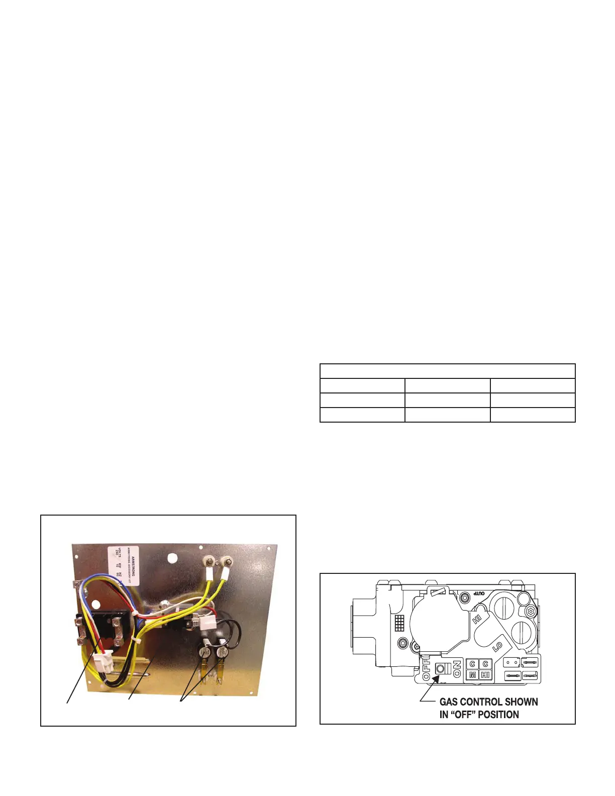
GAS HEAT
Gas Valve (GV1) LRP16GE Units
The LRP16GE uses a gas valve manufactured by
White-Rodgers. The valve is two-stage internally redun-
dant to assure safety shut o. If the valve must be re-
placed the same type valve must be used. The valve can
be converted to LP (see options gas specications for LP
kit) and is adjustable on both high and low re.
24VAC and gas control knob / switch are located on top
of the valve. Terminals on the gas valve are connected to
wires from the ignition control (A3). Inlet and outlet taps
are located on the valve.
FIGURE 13

 Loading...
