Page 1
WARNING
Improper installation, adjustment, alteration, service
or maintenance can cause property damage, personal
injury or loss of life. Installation and service must be
performed by a licensed professional HVAC installer or
equivalent, service agency, or the gas supplier.
IMPORTANT
The Clean Air Act of 1990 bans the intentional venting of
refrigerant (CFCs, HCFCs and HFCs) as of July 1, 1992.
Approved methods of recovery, recycling or reclaiming
must be followed. Fines and/or incarceration may be
levied for noncompliance.
CAUTION
As with any mechanical equipment, contact with sharp
sheet metal edges can result in personal injury. Take
care while handling this equipment and wear gloves and
protective clothing.
WARNING
Electric Shock Hazard. Can cause injury or
death. Unit must be properly grounded in
accordance with national and local codes.
Line voltage is present at all components when
unit is not in operation on units with single-
pole contactors. Disconnect all remote electric
power supplies before opening access panel.
Unit may have multiple power supplies.
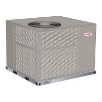
LRP14HP/AC/GE/GN
LRP16GE/HP
Table of Contents
Specications – LRP14HP .............................................2
Specications – LRP14AC ............................................3
Specications – LRP14GE / LRP14GX ......................... 4
Specications – LRP14GN ............................................ 5
Specications – LRP16GE / LRP16GX ......................... 6
Specications – LRP16HP ............................................7
Electric Heat Capacities – LRP14HP and AC Models –
LRP16HP .......................................................................8
Gas Heat Capacities – LRP14GE Only ......................... 8
Gas Heat Capacities – LRP16GE Only ......................... 8
Gas Heat Capacities – LRP14GN Only .........................8
Electrical .......................................................................9
Typical Parts Arrangement ..........................................16
Unit Applications ..........................................................18
Blower Data – LRP14HP .............................................23
Blower Data – LRP14AC ............................................. 24
Blower Data – LRP14GE / LRP14GX...........................25
Blower Data – LRP14GN..............................................26
Blower Data – LRP16GE / LRP16GX...........................27
Blower Data – LRP16HP ..............................................28
Wiring Diagrams and Sequence of Operation .............. 35
LRP14GN – Heating Components and Operation........46
Service Literature
UNIT INFORMATION
Corp. 100032
October 7, 2021
LRP14HP/LRP14AC/LRP14GE/LRP14GN/LRP16GE/LRP16HP SERIES UNITS
The LRP14/16 series packaged units are available in siz-
es ranging from 2 through 5 tons (7.0 through 17.6 kW).
The LRP14/16 unit is designed for HFC-410A refrigerant
and for outdoor residential use only. Units can be installed
at ground level or on rooftops. The LRP14 units utilize a
scroll compressor. LRP16GE/GX/HP units utilize a two-
stage compressor. Information contained in this manual is
intended for use by qualied service technicians only. All
specications are subject to change. Procedures outlined
in this manual are presented as a recommendation only
and do not supersede or replace local or state codes.


 Loading...