Page 21
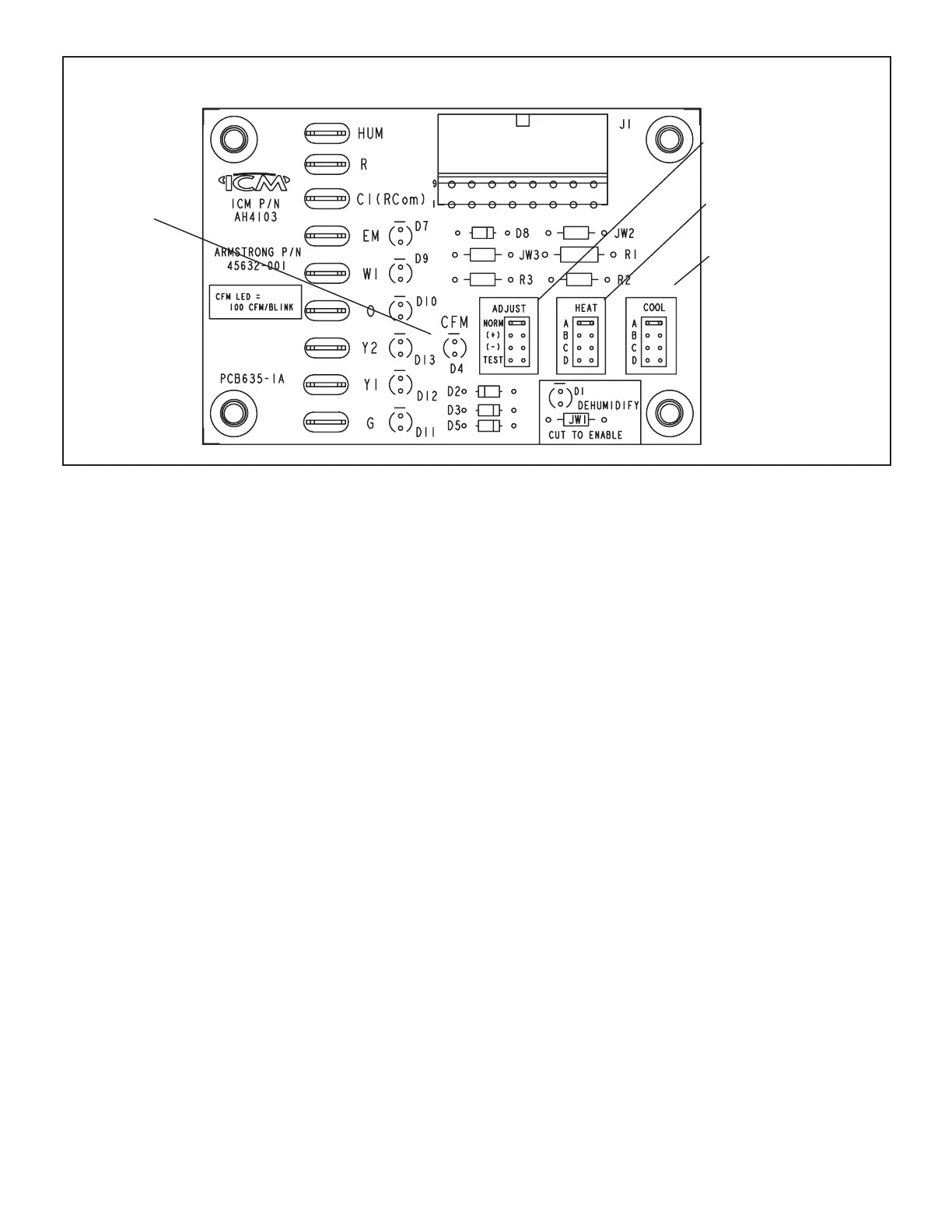
BLOWER CONTROL BOARD (A54) – LRP16 UNITS
(Setting affects both heat−
ing and cooling modes)
DIAGNOSTIC
LED
HEATING SPEED
SELECTOR PINS
COOLING SPEED
SELECTOR PINS
SELECTOR PINS
ADJUST
FIGURE 9. Blower Control Board (A54) – ECM Motor – LRP16GE / LRP16HP
Blower Control – Units with Constant Torque Motors
LRP14 units that are equipped with constant torque blow-
er motors are energized from the W, G and Y 24 volt ter-
minals from the room thermostat, which are connected to
the control board in each unit. The constant torque mo-
tor is capable of maintaining a specied CFM throughout
the external static range. Constant torque units are not
equipped with a separate blower control.
BLOWER SPEED ADJUSTMENT / OPERATION LRP14
UNITS
Blower Speeds – Constant Torque Units
Fan speed on units equipped with constant torque motors
is eld-adjustable. See blower CFM chart for unit size.
Blower Speeds — LRP16GE/HP Units
Fan speed on the HEAT and COOL stage air volume se-
lections are made by jumper pins.
Continuous Fan Operation
When the thermostat is set for “Continuous Fan” operation
and there is no demand for heating or cooling, the blower
on units with PSC motors will operate at cooling speed.
On units with constant torque motors, the blower will oper-
ate at low speed with a G call.
NOTE - With the proper thermostat and sub-base, con-
tinuous blower operation is possible by closing the R to
G circuit. Cooling blower delay is also functional in this
mode.
Blower Control Board (A54) LRP16GE/HP Units
These units are equipped with a variable-speed motor
which is controlled by a blower control board. See gure
11.
On LRP16GE/HP units equipped with ECM motor and a
two-stage electronic blower control, the indoor blower is
energized by the ignition control.
The variable speed motor that is capable of maintaining
a specied CFM throughout the external static range. A
particular CFM can be obtained by positioning jumpers
(COOL, HEAT, and ADJUST) on the blower control board.
The HEAT and COOL jumpers are labeled A, B, C and D.
Each of the letters corresponds with an air volume (CFM)
setting. The ADJUST jumper is labeled NORM, +, - and
Test. The + and - pin settings are used to add or subtract a
percentage of the CFM selected. The Test jumper is used
to operate the motor in the test mode. See gure 11.
Factory settings for the blower speed jumpers are given in
the wiring diagram in gure 11. Use the blower data tables
in this manual to determine the correct air volume for op-
eration in heat and cool mode.
The CFM LED located on the blower control board ashes
one time per 100 cfm to indicate selected blower speed.
For example, if the unit is operating at 1000 CFM, CFM
LED will ash 10 times. If the CFM is 1150, CFM LED will
ash 11 full times plus one fast or half ash.