Page 13
Never connect a Category I appliance to a chimney that is
servicing a solid-fuel appliance. If a replace chimney ue
is used to vent this appliance, the replace opening must
be permanently sealed.
A type B or listed chimney lining system that passes
through an unused masonry chimney ue is not consid-
ered to be exposed to the outdoors.
General Venting Requirements
Vent all ML180DF furnaces according to these instruc-
tions:
1 - Vent diameter recommendations and maximum
allowable piping runs are found in the provided
venting tables.
2 - In no case should the vent or vent connector
diameter be less than the diameter specied in the
provided venting tables.
3 - The minimum vent capacity determined by the
sizing tables must be less than the low re input
rating and the maximum vent capacity must be
greater than the high re input rating.
4 - Single appliance vents - If the vertical vent or tile-
lined chimney has a larger diameter or ow area than
the vent connector, use the vertical vent diameter to
determine the minimum vent capacity and the vent
connector diameter to determine the maximum vent
capacity. The ow area of the vertical vent, however,
shall not exceed 7 times the ow area of the listed
appliance categorized vent area, drafthood outlet
area or ue collar area unless designed according
to approved engineering methods.
5 - Multiple appliance vents - The ow area of the
largest section of vertical vent or chimney shall
not exceed 7 times the smallest listed appliance
categorized vent area, drafthood outlet area or ue
collar area unless designed according to approved
engineering methods.
6 - The entire length of single wall metal vent connector
shall be readily accessible for inspection, cleaning,
and replacement.
7 - Single appliance venting congurations with zero
lateral lengths (table 5) are assumed to have
no elbows in the vent system. For all other vent
congurations, the vent system is assumed to have
two 90° elbows. For each additional 90° elbow or
equivalent (for example two 45° elbows equal one
90° elbow) beyond two, the maximum capacity
listed in the venting table should be reduced by
10% (0.90 x maximum listed capacity).
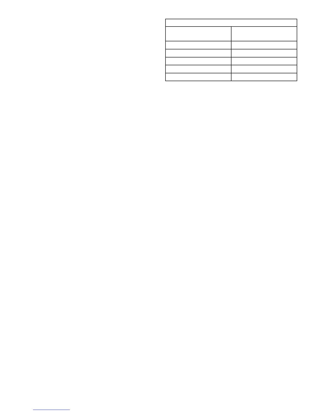
8 - The common venting tables (6 and 7) were
generated using a maximum horizontal vent
connector length of 1-1/2 feet (.46 m) for each inch
(25 mm) of connector diameter as follows:
NOTE - Single Wall Vent Connectors may be used if the
requirements set forth by the National Fuel Gas Code
are met. Please consult latest edition of NFPA 54/ANSI
Z223.1 for proper sizing and application.
TABLE 4
Connector Diameter
inches (mm)
Maximum Horizontal
Connector Length feet (m)
3 (76) 4-1/2 (1.37)
4 (102) 6 (1.83)
5 (152) 7-1/2 (2.29)
6 (152) 9 (2.74)
7 (178)
10-1/2 (3.20)
9 - If the common vertical vent is offset, the maximum
common vent capacity listed in the common venting
tables should be reduced by 20%, the equivalent
of two 90° elbows (0.80 x maximum common vent
capacity). The horizontal length of the offset shall
not exceed 1-1/2 feet (.46 m) for each inch (25 mm)
of common vent diameter.
10 - The vent pipe should be as short as possible with
the least number of elbows and angles required to
complete the job. Route the vent connector to the
vent using the shortest possible route.
11 - A vent connector shall be supported without any
dips or sags and shall slope a minimum of 1/4 inch
(6.4 mm) per linear foot (305 mm) of connector,
back toward the appliance.
12 - Vent connectors shall be rmly attached to the
furnace ue collar by self-drilling screws or other
approved means, except vent connectors of listed
type B vent material which shall be assembled
according to the manufacturer’s instructions. Joints
between sections of single wall connector piping
shall be fastened by screws or other approved
means.
13 - When the vent connector used for Category I
appliances must be located in or pass through a
crawlspace or other areas which may be cold, that
portion of the vent connector shall be constructed
of listed double-wall type B vent material or material
having equivalent insulation qualities.
14 - All venting pipe passing through oors, walls, and
ceilings must be installed with the listed clearance
to combustible materials and be re stopped
according to local codes. In absence of local codes,
refer to NFGC (Z223.1).
15 - No portion of the venting system can extend into,
or pass through any circulation air duct or plenum.
16 - Vent connectors serving Category I appliances shall
not be connected to any portion of mechanical draft
systems operating under positive pressure such as
Category III or IV venting systems.
17 - If vent connectors are combined prior to entering
the common vent, the maximum common vent
capacity listed in the common venting tables must
be reduced by 10%, the equivalent of one 90° elbow
(0.90 x maximum common vent capacity).
18 - The common vent diameter must always be at least
as large as the largest vent connector diameter.
 Loading...