Page 16
11. Combustion Air Inducer Pressure Switch (S18)
ML180UHE(X) series units are equipped with a combus-
tion air pressure switch located on the combustion air in-
ducer orice bracket. The switch is connected to the com-
bustion air inducer housing by means of a exible silicone
hose. It monitors negative air pressure in the combustion
air inducer housing.
The switch is a single-pole single-throw proving switch
electrically connected to the furnace control. The purpose
of the switch is to prevent burner operation if the com-
bustion air inducer is not operating or if the ue becomes
obstructed.
On start-up, the switch senses that the combustion air
inducer is operating. It closes a circuit to the integrated
control when pressure inside the combustion air inducer
decreases to a certain set point. Set points vary depend-
ing on unit size. See table 8. The pressure sensed by
the switch is negative relative to atmospheric pressure.If
the ue becomes obstructed during operation, the switch
senses a loss of negative pressure (pressure becomes
more equal with atmospheric pressure) and opens the cir-
cuit to the integrated control and gas valve. A bleed port
on the switch allows relatively dry air in the vestibule to
purge switch tubing, to prevent condensate build up.
TABLE 8
Unit
inches wc
Make
Break + 0.05
045E36A-1, -2, -54 -0.75 -0.65
070E36B-1, -2 -0.83 -0.68
070E36B-54 -0.85 -0.70
090E48B, 090E60C-1, -2 -0.80 -0.65
090E48B-54 -0.85 -0.70
110E60C-1, -2 -0.83 -0.68
110E60C-54 -0.85 -0.70
135E60D-1, -2, -54 -0.80 -0.65
The switch is factory set and is not eld adjustable. It is a
safety shut-down control in the furnace and must not be
bypassed for any reason. If switch is closed or by-passed,
the integrated control will not initiate ignition at start up.
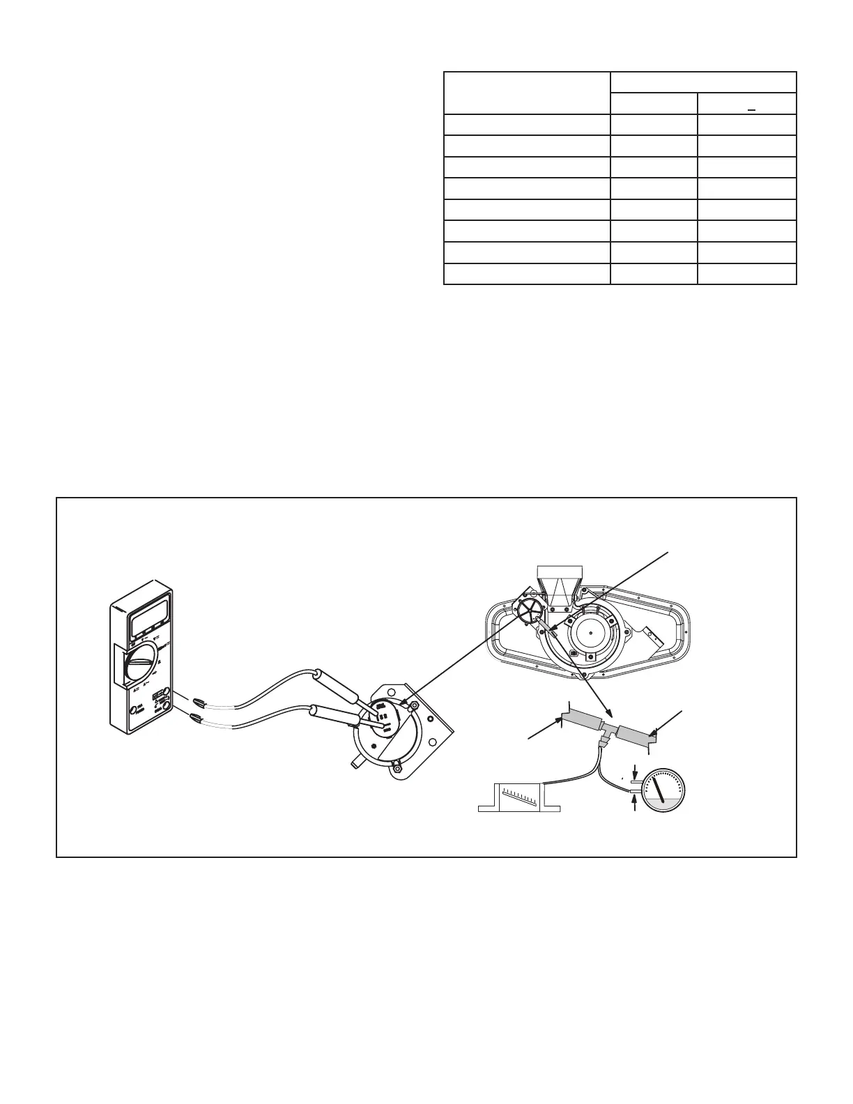
Troubleshooting
See gure 10 for measuring operating pressure and
checking resistance in the pressure switch.
MULTI−METER
SET TO MEASURE OHMS
+
-
or
Field Provided
Tubing To CAI Port
To Pressure Switch
Remove tubing from CAI and
insert “Tee” and additional tubing.
High
Low
FIGURE 10
 Loading...