Page 25
Defrost Control Timing Pins
Each timing pin selection provides a different
accumulated compressor run time period during one
thermostat run cycle. This time period must occur before
a defrost cycle is initiated. The defrost interval can be
adjusted to 30 (T1), 60 (T2), or 90 (T3) minutes. (See
Figure 17 on page 25). The defrost timing jumper is
factory−installed to provide a 60−minute defrost interval.
If the timing selector jumper is not in place, the control
defaults to a 90−minute defrost interval. The maximum
defrost period is 14 minutes and cannot be adjusted.
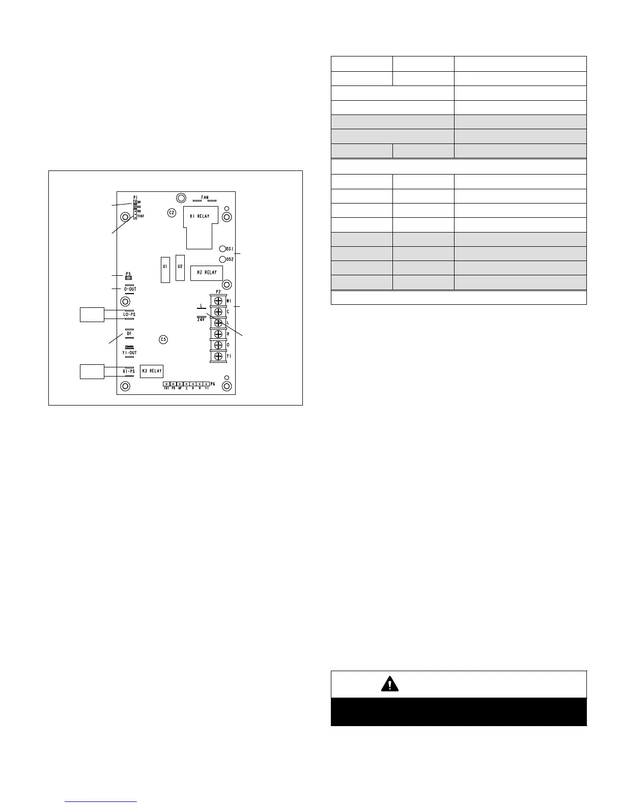
24V TERMINAL
STRIP
CONNECTIONS
DIAGNOSTIC
LEDS
HIGH PRESSURE
SWITCH
TEST
PINS
FIELD SELECT
TIMING PINS
REVERSING
VALVE
DEFROST
THERMOSTAT
LOW PRESSURE
SWITCH
COMPRESSOR
DELAY PINS
S4
S87
SERVICE LIGHT
CONNECTIONS
Figure 17. Outdoor Unit Defrost Control Board
Compressor Delay
The defrost board has a field−selectable function to reduce
occasional sounds that may occur while the unit is cycling
in and out of the defrost mode. When the compressor
delay jumper is removed, the compressor will be cycled off
for 30 seconds going in and out of the defrost mode.
NOTE The 30-second compressor feature is ignored
when TEST pins are jumped.
Test Mode
A TEST option is provided for troubleshooting. See Figure
18 for this function.
Time Delay
The timed−off delay is five minutes long. The delay helps
protect the compressor from short−cycling in case the
power to the unit is interrupted or a pressure switch opens.
The delay is bypassed by placing the timer select jumper
across the TEST pins for 0.5 seconds.
NOTE The board must have a thermostat demand for
the bypass function.
Diagnostic LEDs
The defrost board uses two LEDs for diagnostics. The
LEDs flash a specific sequence according to the diagnosis.
See Table 8.
Table 8. Defrost Control Board Diagnostic LEDs
DS2 Green DS1 Red Condition
OFF OFF Power problem
Simultaneous Slow Flash Normal operation
Alternating Slow Flash 5−minute anti−short cycle delay
Simultaneous Fast Flash Ambient Sensor Problem
Alternating Fast Flash Coil Sensor Problem
ON ON Circuit Board Failure
Fault and Lockout Codes
OFF Slow Flash Low Pressure Fault
OFF ON Low Pressure Lockout
Slow Flash OFF High Pressure Fault
ON OFF High Pressure Lockout
Slow Flash ON Discharge Line Temp. Fault
Fast Flash ON Discharge Line Temp. Lockout
OFF Fast Flash Discharge Sensor Fault
Fast Flash OFF Discharge Sensor Lockout
Shaded entries apply to demand boards only.
Pressure Switch Circuits
The defrost control includes two pressure switch circuits.
The factory−installed high pressure switch (S4) wires are
connected to the board’s HI PS terminals (Figure 17). The
board also includes LO PS terminals to accommodate a
field−provided low (or loss-of-charge) pressure switch.
During a single thermostat cycle, the defrost control will
lock out the unit after the fifth time that the circuit is
interrupted by any pressure switch that is wired to the
control board. In addition, the diagnostic LEDs will indicate
a pressure switch lockout after the fifth occurrence of an
open pressure switch (see Table 8). The unit will remain
locked out until power is broken then remade to the control
or until the jumper is applied to the TEST pins for 0.5
seconds.
NOTE The defrost control board ignores input from the
low pressure switch terminals during the TEST mode,
during the defrost cycle, during the 90−second start−up
period, and for the first 90 seconds each time the reversing
valve switches heat/cool modes. If the TEST pins are
jumpered and the 5−minute delay is being bypassed,
the LO PS terminal signal is not ignored during the
90−second start−up period.
Service Light Connection
The defrost control board includes terminal connections
for a service light which provides a signal that activates the
room thermostat service light during periods of inefficient
operation.
IMPORTANT
NOTE − After testing has been completed, properly re-
position test jumper across desired timing pins.
 Loading...