Page 14
ºF (ºC)* −018 −024 −030 −036 −042 −048 −060
65 (18) 3 (1.7) 5 (2.8) 4 (2.2) 5 (2.8) 6 (3.3) 7 (3.9) 8 (4.4)
75 (24) 5 (2.8) 6 (3.3) 5 (2.8) 5 (2.8) 8 (4.4) 8 (4.4) 9 (5.0)
85 (29) 6 (3.3) 6 (3.3) 6 (3.3) 6 (3.3) 8 (4.4) 8 (4.4) 9 (5.0)
95 (35) 6 (3.3) 7 (3.9) 6 (3.3) 6 (3.3) 8 (4.4) 8 (4.4) 9 (5.0)
105 (41) 6 (3.3) 6 (3.3) 6 (3.3) 5 (2.8) 8 (4.4) 8 (4.4) 9 (5.0)
115 (45) 6 (3.3) 6 (3.3) 6 (3.3) 6 (3.3) 8 (4.4) 9 (5.0) 9 (5.0)
*Temperature of air entering outdoor coil
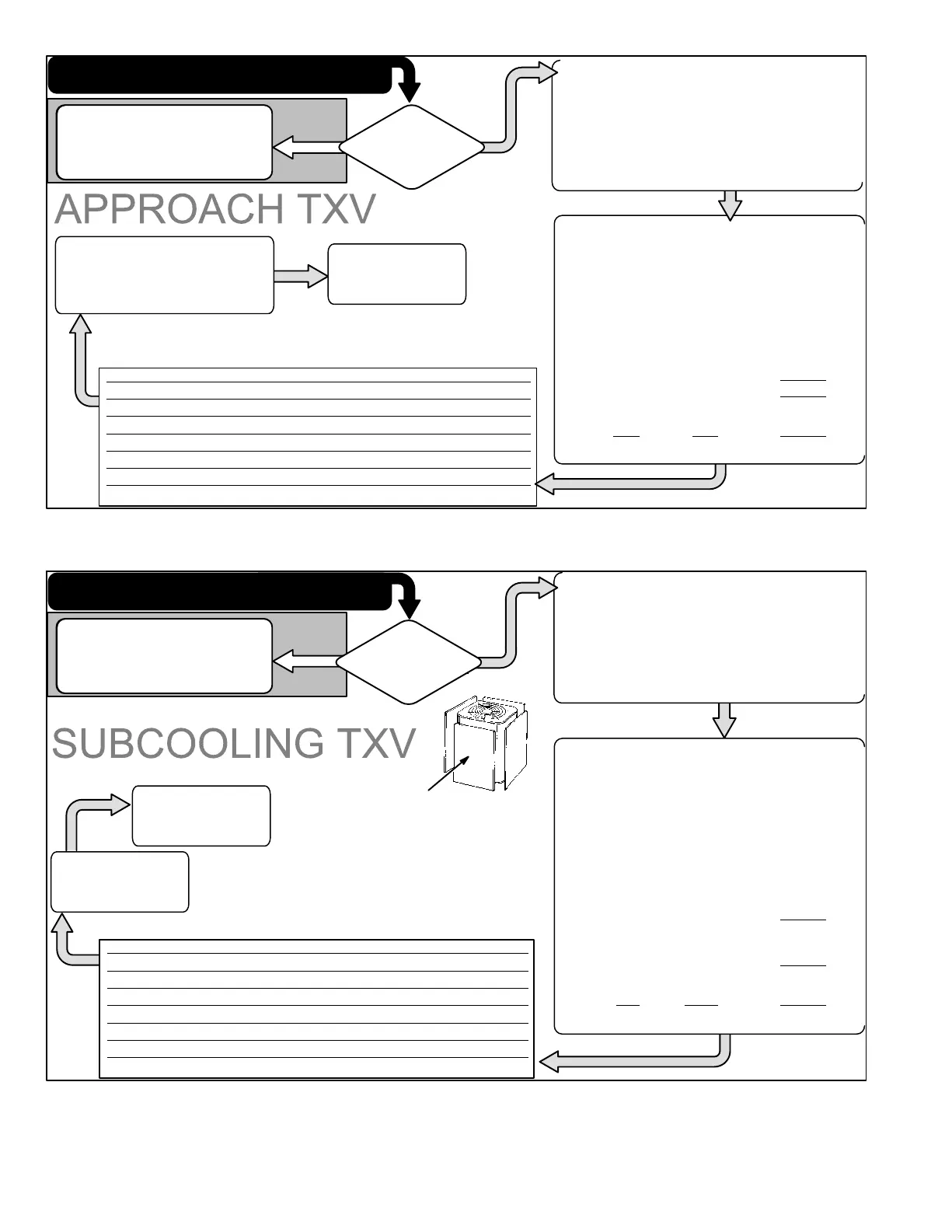
APPROACH METHOD
Set thermostat to call for heat (must have a
cooling load between 70-80ºF (21−26ºC)
Connect gauge set
When heat demand is satisfied, set
thermostat to call for cooling
Allow temperatures and pressures to
stabilize
Record outdoor ambient
temperature AMBº =
Record line temp. LIQº =
Subtract to determine approach (APPº):
LIQº − AMBº = APPº
Compare results with table
DO NOT CHARGE UNIT
(Results of charging at low
temperatures not reliable)
ABOVE
START: Measure outdoor ambient temperature
BELOW
Check Liquid and Vapor line pressures
Compare unit pressures with Normal
Operating Pressures table 4, page 15.
(Table 4 is a general guide. Expect minor pressures
variations. Significant differences may mean improp-
er charge or other system problem.)
Use APPROACH to correctly charge unit or
to verify the charge is correct.
USE WEIGH-IN METHOD
Weigh-in or remove refriger-
ant based upon line length
APPº (Approach) Values(F:+/−1.0°; [C: +/−0.5°])
Above or
below 65ºF
(18ºC)?
If refrigerant added or
removed, retest to
confirm that unit is
properly charged
If value is greater than shown (high
approach), add refrigerant; if less
than shown (liquid temp too close to
ambient temp, low approach), remove
refrigerant.
FIGURE 15 Charging TXV units with Approach Method
DO NOT CHARGE UNIT
(Results of charging at low
temperatures not reliable)
ABOVE
START: Measure outdoor ambient temperature
BELOW
Check Liquid and Vapor line pressures
Compare unit pressures with Normal
Operating Pressures table 4, page 15.
(Table 4 is a general guide. Expect minor pressures
variations. Significant differences may mean improp-
er charge or other system problem.)
Use SUBCOOLING to correctly charge unit
or to verify the charge is correct.
USE WEIGH-IN METHOD
Weigh-in or remove refriger-
ant based upon line length
SUBCOOLING METHOD
Set thermostat to call for heat (must have a
cooling load between 70-80ºF (21−26ºC)
Connect gauge set
Measure outdoor ambient temperature
When heat demand is satisfied, set
thermostat to call for cooling
Allow temperatures and pressures to
stabilize [NOTE − IF NECESSARY, block
outdoor coil to maintain 325 − 375 psig]
Record line temp. LIQº =
Record liquid line pressure; use value to
determine saturation temperature
(table 5 on page 15) SATº =
Subtract to determine subcooling (SCº):
SATº − LIQº = SCº
Compare results with table
ºF (ºC)* −018 −024 −030 −036 −042 −048 −060
65 (18) 10 (5.6) 10 (5.6) 10 (5.6) 11 (6.1) 10 (5.6) 8 (4.4) 8 (4.4)
75 (24) 6 (3.3) 8 (4.4) 8 (4.4) 11 (6.1) 7 (3.9) 8 (4.4) 7 (3.9)
85 (29) 6 (3.3) 8 (4.4) 7 (3.9) 11 (6.1) 7 (3.9) 8 (4.4) 8 (4.4)
95 (35) 6 (3.3) 8 (4.4) 7 (3.9) 10 (5.6) 7 (3.9) 8 (4.4) 7 (3.9)
105 (41) 6 (3.3) 8 (4.4) 7 (3.9) 10 (5.6) 7 (3.9) 8 (4.4) 7 (3.9)
115 (45) 6 (3.3) 8 (4.4) 6 (3.3) 9 (5.0) 7 (3.9) 7 (3.9) 6 (3.3)
*Temperature of air entering outdoor coil
SCº (Subcooling) Values (F:+/−1.0°; [C: +/−0.5°])
Above or
below 65ºF
(18ºC)?
If refrigerant added or
removed, verify
charge using the
approach method
BLOCK OUTDOOR COIL
[sometimes necessary with lower temperatures]
Use cardboard or plastic sheet to restrict the
airflow through the outdoor coil to achieve pres-
sures from 325−375 psig (2240−2585 kPa).
Higher pressures are needed to check charge.
Block equal sections of air intake panels and
move coverings sideways until the liquid pres-
sure is in the above noted ranges.
If value is greater than
shown, remove
refrigerant; if less than
shown, add refrigerant
FIGURE 16 Charging TXV units with Subcooling Method
 Loading...