01/06 505,095M
*2P0106* *P505095M*
Page 1
E2006 Lennox Industries Inc.
Dallas, Texas, USA
RETAIN THESE INSTRUCTIONS
FOR FUTURE REFERENCE
WARNING
Improper installation, adjustment, alteration, ser-
vice or maintenance can cause property damage,
personal injury or loss of life. Installation and ser-
vice must be performed by a qualified installer or
service agency.
IMPORTANT
This unit must be matched with an indoor coil as
specified in Lennox’ Engineering Handbook.
Coils previously charged with R−22 must be flu-
shed.
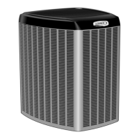
XC15 Outdoor Unit
XC15 outdoor units use R−410A refrigerant. This unit must
be installed with a matching indoor coil and line set as out-
lined in the Lennox Engineering Handbook. XC15 outdoor
units are designed for use in expansion valve (TXV) sys-
tems only. Refer to the Lennox Engineering Handbook for
expansion valve kits which must be ordered separately.
CAUTION
Physical contact with metal edges and corners
while applying excessive force or rapid motion can
result in personal injury. Be aware of, and use
caution when working near these areas during
installation or while servicing this equipment.
Shipping and Packing List
1 − Assembled XC15 outdoor unit
1 − Bushing (for low voltage wiring)
2 − Grommets (for liquid and vapor lines)
Check equipment for shipping damage. If you find any
damage, immediately contact the last carrier.
INSTALLATION
INSTRUCTIONS
XC15 Series Units
CONDENSING UNITS
505,095M
01/06
Table of Contents
XC15 Outdoor Unit 1. . . . . . . . . . . . . . . . . . . . . . . . . . . . . .
Shipping And Packing List 1. . . . . . . . . . . . . . . . . . . . . . . .
Unit Dimensions 2. . . . . . . . . . . . . . . . . . . . . . . . . . . . . . . . .
General Information 1. . . . . . . . . . . . . . . . . . . . . . . . . . . . .
Setting Unit 2. . . . . . . . . . . . . . . . . . . . . . . . . . . . . . . . . . . . .
Removing Panels 3. . . . . . . . . . . . . . . . . . . . . . . . . . . . . . .
Electrical 4. . . . . . . . . . . . . . . . . . . . . . . . . . . . . . . . . . . . . . .
Refrigerant Piping 6. . . . . . . . . . . . . . . . . . . . . . . . . . . . . . .
Flushing Existing Line Set and Indoor Coil 9. . . . . . . . . .
Refrigerant Metering Device 10. . . . . . . . . . . . . . . . . . . . .
Manifold Gauge Set 11. . . . . . . . . . . . . . . . . . . . . . . . . . . .
Service Valves 11. . . . . . . . . . . . . . . . . . . . . . . . . . . . . . . . .
Leak Testing 12. . . . . . . . . . . . . . . . . . . . . . . . . . . . . . . . . . .
Evacuation 12. . . . . . . . . . . . . . . . . . . . . . . . . . . . . . . . . . . .
Start−up 13. . . . . . . . . . . . . . . . . . . . . . . . . . . . . . . . . . . . . . .
Refrigerant Charging 13. . . . . . . . . . . . . . . . . . . . . . . . . . . .
System Operation 16. . . . . . . . . . . . . . . . . . . . . . . . . . . . . .
Maintenance 18. . . . . . . . . . . . . . . . . . . . . . . . . . . . . . . . . . .
Optional Accessories 18. . . . . . . . . . . . . . . . . . . . . . . . . . .
XC15 Start−Up and Performance Check List 19. . . . . . . .
Homeowner’s Information − Maintenance 19. . . . . . . . . .
Thermostat Operation 20. . . . . . . . . . . . . . . . . . . . . . . . . . .
Sound Reduction Cover & Assembly Procedure 20. . . .
General Information
When servicing or repairing HVAC components, ensure
the fasteners are appropriately tightened. Table 1 shows
torque values for fasteners, and for port and valve caps.
Table 1
Torque Requirements
Part Recommended Torque
Service valve cap 8 ft.− lb. 11 NM
Sheet metal screws 16 in.− lb. 2 NM
Machine screws #8 16 in.− lb. 2 NM
Compressor bolts 90 in.− lb. 10 NM
Gauge port seal cap 8 ft.− lb. 11 NM
These instructions are intended as a general guide and do
not supersede national or local codes in any way. Consult
authorities having jurisdiction before installation.
Litho U.S.A.