Page 2
505095M 1/3/06
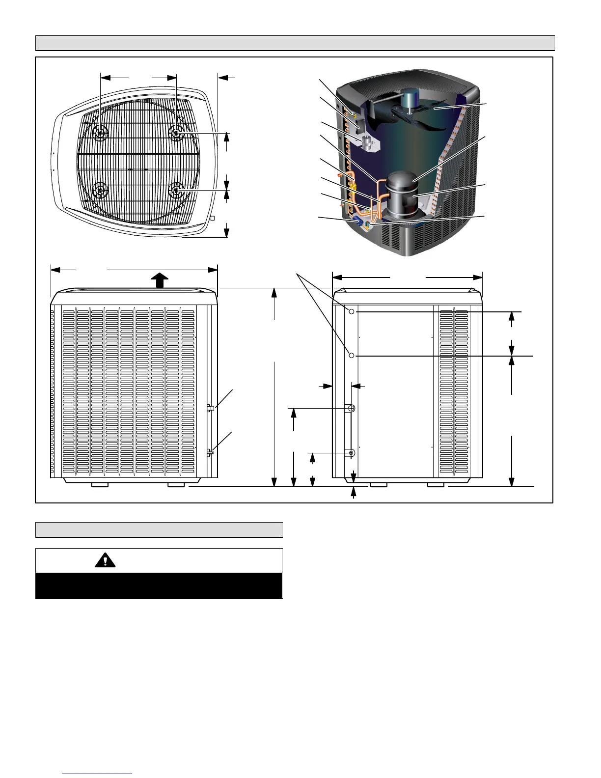
Unit Dimensions − inches (mm) and Parts Arrangement
39−1/2
(1003)
35−1/2
(902)
18−5/8
(473)
8 (203)
1 (25)
4−7/16
(113)
LIQUID
LINE
INLET
SUCTION
LINE
INLET
ELECTRICAL
INLETS
TOP VIEW
SIDE VIEW ACCESS VIEW
DISCHARGE AIR
CONTACTOR
SYSTEM OPERA-
TION MONITOR
RUN CAPACITOR
DISCHARGE LINE
VAPOR VALVE AND
GAUGE PORT
VAPOR LINE
LOW PRESSURE
SWITCH
FILTER DRIER
OUTDOOR FAN
COMPRESSOR
AND SOUND
REDUCTION
COVER (SEE
PAGE 20 FOR
COVER
INFORMATION)
COMPRESSOR
TERMINAL
PLUG
HIGH
PRESSURE
SWITCH
Figure 1
37 (940)
[−024 thru −042]
47 (1194)
[−048 and −060]
21−1/8 (537)
[−024 thru −042]
31−1/8 (791)
[−048 and −060]
10−3/8 (264)
10−1/2
(267)
13−1/2
(343)
9−1/4
(234)
18
(457)
Setting the Unit
CAUTION
In order to avoid injury, take proper precaution when
lifting heavy objects.
Refer to unit dimensions for sizing mounting slab, plat-
forms or supports. Refer to figure 2 for installation clear-
ances.
Service Panel Clearance
A service clearance of 30" (762 mm) must be maintained
on the access panel side of the unit (see figure 2).
 Loading...