Page 36
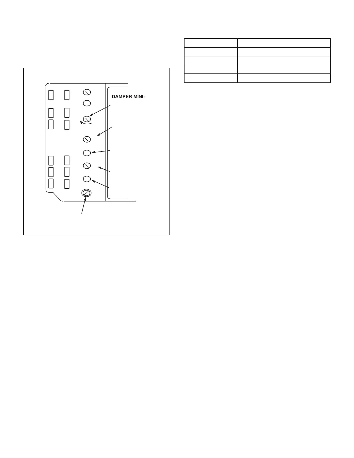
A6 Enthalpy Control LED’S
is suitable for free cooling. When an optional IAQ sensor
IAQ reading is higher than setpoint requiring more fresh
A
B
C
D
Open
Min
Pos
FREE COOLING SETPOINT;
A=Completely counterclockwise
OUTDOOR AIR
SUITABLE LED
Free
Cool
DCV
EXH
EXH
Set
2V 10V
DCV
Max
2V 10V
DCV
Set
2V 10V
IAQ SETPOINT
IAQ READING IS
ABOVE SETPOINT
MUM POSITION
IAQ MAXIMUM
POSITION
(set higher than
minimum position)
FIGURE 20
Free Cooling Setpoint
Outdoor air is considered suitable when temperature and
humidity are less than the free cooling setpoints shown
A6 enthalpy control free cooling setpoint potentiometer
TABLE 9
ENTHALPY CONTROL SETPOINTS
Control Setting
A
B
C
D
Damper Minimum Position
NOTE - A jumper is factory-installed between TB1 R and
OC terminals to maintain occupied status (allowing min-
imum fresh air). When using an electronic thermostat or
energy management system with an occupied/unoccu-
pied feature, remove jumper.
1 - Set thermostat to occupied mode if the feature is
available. Make sure jumper is in place between
does not have the feature.
2 -
desired fresh air percentage.
Note - Damper minimum position can be set lower
than traditional minimum air requirements when
an IAQ sensor is specied. Dampers will open to
DCV MAX setting (if CO2 is above setpoint) to meet
traditional ventilation requirements.
3 - Measure outdoor air temperature. Mark the point on
4 - Measure return air temperature. Mark that point on
temperature. Mark that point on the top line of chart
6 - Draw a straight line between points A and B.
7 - Draw a vertical line through point C.
8 - Draw a horizontal line where the two lines meet.
MIN POS SET potentiometer higher. If fresh air
until calculation reads desired fresh air percentage
 Loading...