EasyManua.ls Logo

Lennox ZCC Series - User Manual

Lennox ZCC Series
49 pages
To Next Page IconTo Next Page
Loading...
Page 1
UNIT INFORMATIONUNIT INFORMATION
Service Literature
WARNING
Electric shock hazard. Can cause injury
or death. Before attempting to perform
any service or maintenance, turn the
electrical power to unit OFF at disconnect
switch(es). Unit may have multiple power
supplies.
Table of Contents
Options / Accessories . . . . . . . . . . . . . . . . . . . . . . . Page 2

Blower Data . . . . . . . . . . . . . . . . . . . . . . . . . . . . . . . . Page 6
Electrical Data /Electric Heat Data . . . . . . . . . . . . Page 10

I- Unit Components . . . . . . . . . . . . . . . . . . . . . . . Page 16
II- Placement and Installation . . . . . . . . . . . . . . . Page 27
III- Start-Up . . . . . . . . . . . . . . . . . . . . . . . . . . . . . . . Page 27
IV- Charging . . . . . . . . . . . . . . . . . . . . . . . . . . . . . . Page 28
V- System Service Checks . . . . . . . . . . . . . . . . . Page 33
VI- Maintenance . . . . . . . . . . . . . . . . . . . . . . . . . . . Page 33
VII- Accessories . . . . . . . . . . . . . . . . . . . . . . . . . . . . Page 34
VIII-Wiring Diagrams . . . . . . . . . . . . . . . . . . . . . . . . Page 41

packaged electric units are available in standard cooling
󰀩
󰀨-
ent energy management thermostat control systems with
-
tions connect to the unit with jack plugs. When ”plugged
in” the controls become an integral part of the unit wiring.
       -
erates in single or multiple stages depending on the kW

ZCC units.
Information contained in this manual is intended for use

subject to change. Procedures outlined in this manual are
presented as a recommendation only and do not super-
sede or replace local or state codes.



for the proper rigging technique.
WARNING
Improper installation, adjustment, alteration,
service or maintenance can cause property damage,
personal injury or loss of life. Installation and service
must be performed by a licensed professional HVAC
installer or equivalent service agency.
WARNING
To prevent serious injury or death:
1- Lock-out/tag-out before performing maintenance.
2- If system power is required (e.g., smoke detector
maintenance), disable power to blower, remove
fan belt where applicable, and ensure all
controllers and thermostats are set to the “OFF”
position before performing maintenance.
3- Always keep hands, hair, clothing, jewelry, tools,
etc., away from moving parts.
CAUTION
As with any mechanical equipment, contact with
sharp sheet metal edges can result in personal
injury. Take care while handling this equipment and
wear gloves and protective clothing.
ZCC SERIES
7.5 to 12.5 ton
26.3 to 42 kW
100078
ZCC092 through 150
Question and Answer IconNeed help?

Do you have a question about the Lennox ZCC Series and is the answer not in the manual?

Lennox ZCC Series Specifications

General IconGeneral
BrandLennox
ModelZCC Series
CategoryAir Conditioner
LanguageEnglish

Summary

Service Literature

ZCC092 through 150

Identifies the specific unit series covered by the service literature.

OPTIONS; ACCESSORIES

COOLING SYSTEM

Lists available cooling system options and accessories for the unit.

BLOWER - SUPPLY AIR

Details supply air blower options and motor kits for unit configuration.

CABINET

Lists cabinet-related accessories and options for unit customization.

CONTROLS

Lists control system options and accessories for unit operation.

INDOOR AIR QUALITY

Covers air filters and indoor air quality sensors available for the unit.

HUMIDITROL DEHUMIDIFICATION REHEAT OPTION

Describes the Humiditrol® dehumidification option for the unit.

ELECTRICAL

Details electrical options like disconnect switches and GFI outlets.

ELECTRIC HEAT

Lists available electric heat kW capacities and voltage options.

ECONOMIZER

Details standard and high-performance economizer options for the unit.

OUTDOOR AIR

Covers outdoor air damper options and related accessories.

POWER EXHAUST

Lists power exhaust options available for unit installation.

ROOF CURBS

Details available roof curb options for unit mounting.

CEILING DIFFUSERS

Lists ceiling diffuser options for air distribution.

SPECIFICATIONS

General Data

Provides general unit specifications like tonnage, model numbers, and efficiency.

Cooling Performance

Details cooling capacity, airflow, and power consumption for unit models.

Refrigerant Charge

Lists refrigerant types and charge amounts for each unit's circuits.

Electric Heat Available

Indicates the available electric heat sizes for the unit models.

Compressor Type (number)

Specifies the types and quantities of compressors used in the units.

Outdoor Coils

Details specifications for the outdoor coils used in the units.

Outdoor Coil Fans

Lists specifications for the outdoor coil fans.

Indoor Coils

Details specifications for the indoor coils used in the units.

Indoor Blower and Drive Selection

Covers blower motor and drive kit specifications for the units.

Filters

Specifies the types and sizes of filters used in the units.

Electrical characteristics

Outlines electrical characteristics and voltage requirements for the units.

BLOWER DATA

BELT DRIVE - 7.5 | 8.5 TON

Provides blower performance data for 7.5 and 8.5 ton belt drive units.

Minimum Air Volume Required For Use With Optional Electric Heat

Specifies minimum airflow requirements for units with optional electric heat.

BELT DRIVE - 10 | 12.5 TON

Provides blower performance data for 10 and 12.5 ton belt drive units.

FACTORY INSTALLED BELT DRIVE KIT SPECIFICATIONS

Details specifications for factory-installed belt drive kits.

POWER EXHAUST FAN PERFORMANCE

Provides performance data for power exhaust fans used in the units.

FACTORY INSTALLED OPTIONS;FIELD INSTALLED ACCESSORY AIR RESISTANCE

Air resistance data for various factory/field installed options.

CEILING DIFFUSERS AIR RESISTANCE

Provides air resistance data for different ceiling diffuser models.

CEILING DIFFUSER AIR THROW DATA

Details air throw data for various ceiling diffuser models.

ELECTRICAL;ELECTRIC HEAT DATA

7.5 TON

Electrical and electric heat data specific to 7.5 ton unit models.

8.5 ΤΟΝ

Electrical and electric heat data specific to 8.5 ton unit models.

10 ΤΟΝ

Electrical and electric heat data specific to 10 ton unit models.

12.5 ΤΟΝ

Electrical and electric heat data specific to 12.5 ton unit models.

ELECTRICAL ACCESSORIES

Lists electrical accessories such as disconnects and their specifications.

ELECTRIC HEAT CAPACITIES

ZCC PARTS ARRANGEMENT

ZCC CONTROL BOX

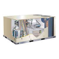
Shows the arrangement of components within the ZCC unit's control box.

I-UNIT COMPONENTS

ELECTROSTATIC DISCHARGE (ESD) Precautions and Procedures

Safety precautions for handling electronic components to prevent ESD damage.

A-Control Box Components

Details the components found inside the ZCC unit's control box.

ZCC PLUMBING AND COMPRESSOR CIRCUITS DETAIL

B-Cooling Components

C-Blower Compartment

OPERATION; ADJUSTMENT

A-Three Scroll Compressor Voltage Phasing

Ensures correct rotation of three-phase scroll compressors and blowers.

B-Blower Operation

Explains how the blower operates based on thermostat settings and demand.

C-Blower Access

Describes how to access the blower assembly for servicing or maintenance.

D-Determining Unit CFM

E-Blower Belt Adjustment

Instructions for adjusting blower belt tension for optimal performance and life.

PULLEY ALIGNMENT

F-Check Belt Tension

Procedure for checking and measuring belt tension accurately.

F-Field-Furnished Blower Drives

Information on selecting and installing field-furnished blower drives.

D-Optional Electric Heat Components

ELECTRIC HEAT CONTROL ASSEMBLY

SINGLE DISCONNECT INSTALLATIONS

ELECTRIC HEAT VESTIBULE PARTS ARRANGEMENT

EHA 7.5, 15, 22.5, 30, 45, 60 KW ELECTRIC HEAT SECTION PARTS ARRANGEMENT

Details the arrangement of components within the electric heat section.

II-PLACEMENT AND INSTALLATION

A-Preliminary and Seasonal Checks

Pre-startup checks for unit installation and wiring integrity.

B-Cooling Startup

Steps for initiating cooling operation based on thermostat demand.

C-Safety or Emergency Shutdown

Procedures for safely shutting down the unit in emergency situations.

Three Phase Scroll Compressor Voltage Phasing

Ensures correct rotation of three-phase scroll compressors and blowers.

IV-CHARGING

REFRIGERANT CHARGE AND CHECK

Procedures for checking and adjusting the unit's refrigerant charge.

V-SYSTEMS SERVICE CHECKS

A-Cooling System Service Checks

Procedures for checking the cooling system's performance and operation.

VI-MAINTENANCE

A-Filters

Information on filter replacement and maintenance schedule.

B-Lubrication

Details on motor lubrication requirements and factory sealing.

C-Evaporator Coil

Instructions for cleaning and inspecting the evaporator coil.

D-Condenser Coil

Instructions for cleaning and inspecting the condenser coil.

VII-ACCESSORIES

A-Mounting Frames

Details on roof mounting frames for unit installation applications.

B-Transitions

Information regarding transitions, which are typically field-provided.

C-Supply and Return Diffusers

Optional diffusers for supply and return air distribution.

D-Economizer (Field or Factory Installed)

Overview of economizer operation for free cooling capabilities.

A6 Enthalpy Control LEDS

DCV Set and Max Settings

Economizer Operation

Explains economizer operation based on thermostat settings and occupancy.

ECONOMIZER OPERATION-OUTDOOR AIR IS SUITABLE FOR FREE COOLING - FREE COOL LED ON

Standard Economizer Down Flow and Horizontal

Wiring

Details wiring connections for the economizer control module.

F-Power Exhaust Fan

Power Exhaust Setpoint Adjustment

Instructions for adjusting the power exhaust fan setpoint.

H-Drain Pan Overflow Switch S149 (option)

Function and control of the drain pan overflow switch.

VIII-Wiring Diagrams and Sequence of Operation

ZCC092;150 UNIT DIAGRAM

Illustrates the electrical wiring diagram for the ZCC092/150 unit.

ZCC092;150 Sequence of Operation

Blower Operation

Explains blower operation based on thermostat signals and demand.

ELECTRONIC OR ELECTROMECHANICAL THERMOSTAT

ECONOMIZER STANDARD EFFICIENCY

ECONOMIZER HIGH PERFORMANCE; LOW LEAK

SEQUENCE OF OPERATION

Outlines the sequence of operation for the high performance economizer.

EHA-7.5, 15, 22.5, 30, 45 & 60 kW Y VOLTAGE ZCC SERIES UNITS

WIRING DIAGRAM

Shows the wiring diagram for electric heat sections (Y voltage).

EHA-7.5, 15, 22.5, 30, 45 & 60 kW G, J VOLTAGE ZCC SERIES UNITS

WIRING DIAGRAM

Shows the wiring diagram for electric heat sections (G, J voltage).

Sequence of Operation - EHA 7.5, 15, 22.5, 30, 45, 60 kW - Y and G, J, M

HEATING ELEMENTS:

Describes the electric heating elements and their protection fuses.

FIRST STAGE HEAT:

Details the operation of the first stage of electric heat.

SECOND STAGE HEAT:

Details the operation of the second stage of electric heat.

SINGLE DISCONNECT INSTALLATIONS

MULTIPLE POWER SUPPLY - NO CB10;S48

Wiring configurations for multiple power supplies without specific breakers.

SINGLE POWER SUPPLY WITH CB10;S48

Wiring configurations for single power supply with circuit breakers.

MULTIPLE POWER SUPPLY WITH CB10;S48

Wiring configurations for multiple power supplies with circuit breakers.

Related product manuals