OPERATION / ADJUSTMENT
A-Three Scroll Compressor Voltage Phasing
Three phase scroll compressors must be phased sequen-
tially to ensure correct compressor and rotation and op-
eration.
NOTE- The VFD that drives the blower motor will automat-
ically correct for incorrect phasing. Do not assume correct
blower rotation with correct phasing.
Compressor and blower are wired in phase at the factory.
1 - Observe suction and discharge pressures and
blower rotation on unit start-up.
is not correct:
2 -
must rise.
3 - Disconnect all remote electrical power supplies.
4 -
at blower contactor or compressors.
Make sure the connections are tight. Discharge and
suction pressures should operate at their normal
start-up ranges.
Discharge and suction pressures should operate at their
normal start-up ranges.
B-Blower Operation
Initiate blower demand at thermostat according to instruc-
tions provided with thermostat. Unit will cycle on thermo-
stat demand. The following steps apply to applications
using a typical electro-mechanical thermostat.
1 - Blower operation is manually set at the thermostat
blowers will operate continuously.
2 -
cycle with demand. Blowers and entire unit will be
C-Blower Access
The blower assembly is secured to a sliding frame which
allows the blower motor to be pulled out of the unit. See
1 - Loosen the reusable wire tie which secures the
blower wiring to the blower motor mounting plate.
2 -
frame. Pull frame toward outside of unit.
3 -
location on the blower motor base using the wire tie.
4 -
frame.
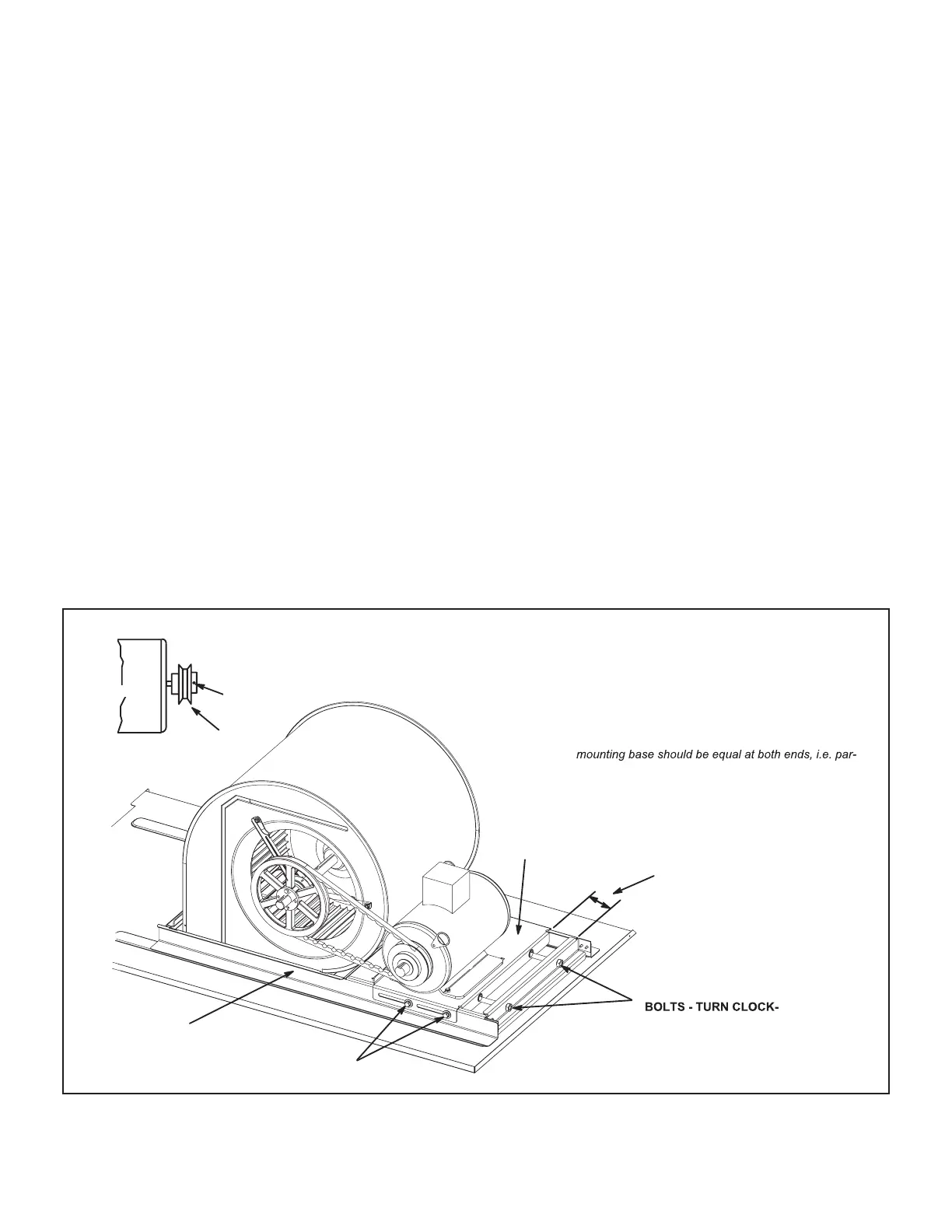
STANDARD BLOWER ASSEMBLY
TO INCREASE BELT TENSION
1- Loosen four bolts securing motor mounting base
to frame.
2- Turn adjusting bolt to the right, or clockwise, to
move the motor away from the blower housing.
IMPORTANT - Gap between end of frame and motor
allel along gap.
3- Tighten four bolts securing motor mounting base
to frame.
4- Relieve tension on two adjusting bolts.
PULLEY
MOTOR
SIDE VIEW
ALLEN
SCREW
BELT ADJUSTING
WISE
TO TIGHTEN BELT
MOTOR
MOUNTING
BASE
LOOSEN BEFORE
ADJUSTING BELT TENSION
(TWO EACH SIDE)
MOTOR
BLOWER
HOUSING
BLOWER
FRAME
GAP BETWEEN EDGES SHOULD
BE PARALLEL ON BOTH ENDS
BEFORE TIGHTENING MOTOR
MOUNTING BASE IN PLACE
FIGURE 5
 Loading...