Page 20
D-Determining Unit CFM
NOTE - Units equipped a Variable Frequency Drive (VFD)
are designed to operate on balanced, three-phase power.
Operating units on unbalanced three-phase power will re-
duce the reliability of all electrical components in the unit.
Unbalanced power is a result of the power delivery system
supplied by the local utility company. Factory-installed in-
verters are sized to drive blower motors with an equiva-
lent current rating using balanced three-phase power. If
unbalanced three-phase power is supplied; the installer
must replace the existing factory-installed inverter with an
inverter that has a higher current rating to allow for the im-
balance. Refer to the installation instructions for additional
information and available replacements.
1 - The following measurements must be made with a
Units Equipped With An Inverter -
Initiate high speed blower without a cooling demand.
2 -
3 -
Blower performance data is based on static pressure
Note - Static pressure readings can vary if not taken
where shown.
4 -
pages 16 and 17 when installing units with any of
the optional accessories listed.
Loosen Allen screw and turn adjustable pulley
minimum and maximum number of pulley turns as
shown in table 1.
6 - Units Equipped With An Inverter -
pressure switches S4 and S7.
TABLE 1
MINIMUM AND MAXIMUM PULLEY ADJUSTMENT
Belt Min Turns Open Max Turns Open
A Section 0
B Section 1* 6
*No minimum number of turns open when B belt is used
on pulleys 6” O.D. or larger.
E-Blower Belt Adjustment
Maximum life and wear can be obtained from belts only if
proper pulley alignment and belt tension are maintained.
Tension new belts after a 24-48 hour period of opera-
tion. This will allow belt to stretch and seat in the pulley
grooves. Make sure blower and motor pulleys are aligned
1 - Loosen four bolts securing motor base to mounting
2 - To increase belt tension -
move the motor outward and tighten the belt. This in-
creases the distance between the blower motor and
the blower housing.
To loosen belt tension -
to loosen belt tension.
IMPORTANT - Align top edges of blower motor base
and mounting frame base parallel before tightening
two bolts on the other side of base. Motor shaft and
blower shaft must be parallel.
3 - Tighten two bolts on each side of the motor mounting
base. This secures the mounting base to the frame
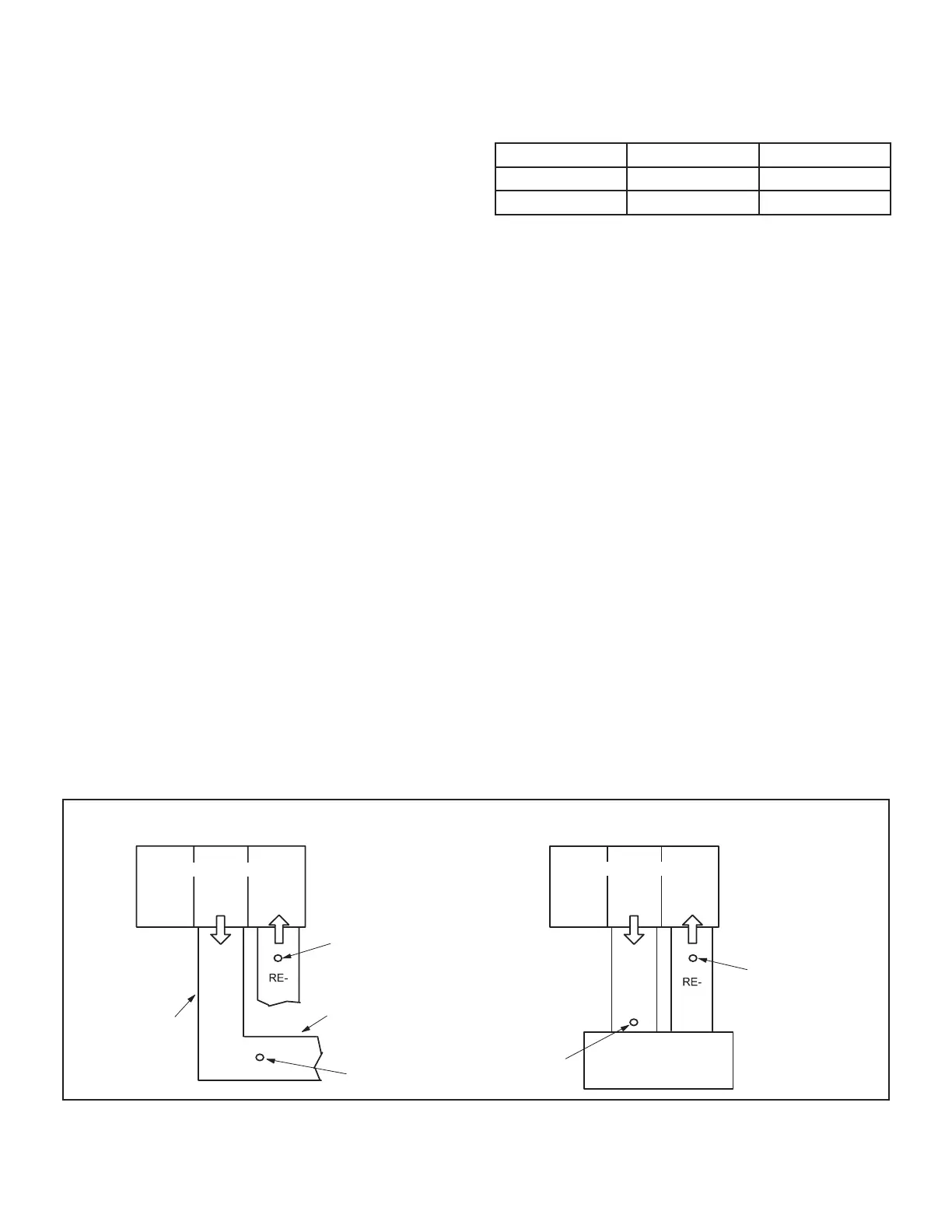
LOCATION OF STATIC PRESSURE READINGS
SUPPLY AIR
READING
LOCATION
SUPPLY
TURN
INSTALLATIONS WITH DUCTWORK
SUPPLY
TURN
INSTALLATIONS WITH CEILING DIFFUSERS
MAIN
DUCT RUN
FIRST BRANCH
OFF OF MAIN RUN
DIFFUSER
ROOFTOP UNIT
ROOFTOP UNIT
SUPPLY AIR
READING
LOCATION
RETURN AIR
READING LOCATION
RETURN AIR
READING
LOCATION
FIGURE 6
 Loading...