Do you have a question about the Lenovo ideacentre 510 Series and is the answer not in the manual?
Key safety guidelines and warnings for manual users, emphasizing caution before proceeding with instructions.
Essential practices for maintaining safety during computer operation and maintenance, including lifting and personal conduct.
Precautions and procedures to prevent hazards from electrical current during service, including power disconnection.
A checklist to identify potentially unsafe conditions on computer products, covering electrical and mechanical hazards.
Procedures to protect sensitive electronic components from ESD damage using grounding and protective measures.
Ensuring proper electrical grounding for operator safety and correct system function is mandatory.
Crucial warnings and cautions related to product safety and operation, including electrical storms and cable handling.
Details the physical and environmental specifications for the computer, including temperature, humidity, and electrical input.
Instructions on how to access and launch the BIOS Setup Utility by pressing the F1 key.
Guidance on navigating and modifying system configuration options within the BIOS Setup Utility menu.
Information on setting and managing Administrator and Power-On passwords for system security and access control.
Details on setting, changing, or deleting Administrator passwords to deter unauthorized configuration changes.
Procedure for setting, changing, or deleting Power-On passwords to protect system startup from unauthorized access.
How to configure system devices by enabling or disabling them via BIOS settings, affecting hardware functionality.
Instructions for choosing the boot device sequence for system startup, either temporarily or permanently.
Procedure to temporarily change the boot device without altering the permanent startup sequence using F12.
Steps to view or permanently modify the order of boot devices within the BIOS Startup option.
Methods for saving or discarding changes and exiting the BIOS Setup Utility program.
Troubleshooting steps and FRU actions for issues related to HDD boot failures, including configuration and drive defects.
Procedures for diagnosing and resolving issues related to the computer's power supply, focusing on connectors and switches.
Understanding and diagnosing Power-On Self-Test (POST) error messages for basic system-board and component checks.
A systematic approach to diagnosing issues where the cause is not immediately clear, by isolating components.
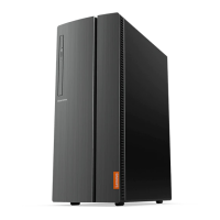
Illustrations and labels for controls and connectors on the front of the computer, including power button and USB ports.
Illustrations and labels for connectors and components on the rear of the computer, such as audio and video ports.
Diagrams and identification of the various internal hardware components of the computer, from power supply to fans.
Diagrams and labels for connectors and components located on the computer's motherboard.
General guidelines and precautions to read and understand before replacing any FRUs or performing repairs.
Essential steps to take before beginning any hardware disassembly, including powering off and unplugging.
Step-by-step instructions for removing and installing the computer's keyboard and mouse.
Procedure for safely removing the computer's outer casing, including loosening securing screws.
Detailed steps for removing and installing the computer's power supply unit, including cable disconnection.
Instructions for detaching and removing the front panel of the computer by releasing plastic tabs.
Procedure for replacing the optical drive (CD/DVD drive) in the computer, involving bezel and cable removal.
Steps to replace the M.2 form factor storage drive, involving motherboard screw removal and careful extraction.
Procedure for replacing the main storage drive (HDD/SSD) in the computer, including drive bay manipulation.
Instructions for replacing the front panel multi-card reader, involving front I/O assembly removal.
Steps to remove and install PCI Express expansion cards, including latch operation and drive bay pivoting.
Procedure for replacing RAM modules (DIMMs) in the computer, involving retaining clip operation and correct alignment.
Instructions for removing and installing the wireless network card, including antenna cable disconnection.
Procedure for replacing the antenna connected to the front of the Wi-Fi card, involving peeling and routing.
Procedure for replacing the antenna connected to the rear of the Wi-Fi card, similar to front antenna replacement.
Steps to remove and install the CPU heat sink and fan assembly, involving screw loosening and thermal grease.
Detailed procedure for replacing the CPU (Central Processing Unit), including retainer and orientation alignment.
Instructions for replacing the front cooling fan in specific models, involving rubber mount manipulation.
Instructions for replacing the rear cooling fan in specific models, involving rubber mount manipulation.
Comprehensive steps for removing and installing the computer's main system board, including component removal.
List of Field Replaceable Units (FRUs) for the ideacentre 510A-15ARR model, including part numbers and descriptions.
| Form Factor | Tower |
|---|---|
| Material | Metal, Plastic |
| Front Ports | 2 x USB 3.0, Headphone |
| Drive Bays | 1 x 3.5", 1 x 2.5" |
| Expansion Slots | 1 x PCIe x16, 1 x PCIe x1 |
| Color | Black |