Do you have a question about the Lenovo ThinkPad X1 2-in-1 Gen 9 and is the answer not in the manual?
General safety guidelines for handling equipment and personnel during maintenance.
Rules for working safely with electrical equipment and preventing shocks.
Checklist for identifying potentially unsafe conditions before servicing a computer.
Precautions and procedures for handling ESD-sensitive components to prevent damage.
Ensures proper electrical grounding for operator safety and system function.
Presents safety notices in multiple languages, including DANGER warnings.
Guidelines and strategies for replacing Field Replaceable Units (FRUs) in the computer.
Recommended procedure for replacing a solid-state drive, including data backup.
Guidance on interpreting and using error codes for diagnosing failures.
Information on model types and FRU identification for different configurations.
Introduction to different model types and how to identify each specific type.
Steps to identify Field Replaceable Units (FRUs) for a specific product.
Essential information and steps to gather before returning a Field Replaceable Unit (FRU).
Procedures to guide in identifying and correcting problems with the notebook computer.
Troubleshooting steps and using diagnostic tools for computer issues.
Running quick tests to troubleshoot and resolve computer problems.
Using the preinstalled UEFI diagnostic program to view system info and test hardware.
Downloading and using bootable diagnostic programs via USB or disc.
Procedures to verify the functionality of the battery or AC power adapter.
Steps to verify if the AC power adapter is functional and properly connected.
Procedures to check the battery status and charging function.
Procedure to check the voltage of the coin-cell battery.
Instructions for resetting or restoring the Windows operating system.
Information on setting and managing system passwords in UEFI BIOS.
Details on the power-on password and how to remove it.
Information on NVMe passwords and their security features.
Security features of the supervisor password and its administration.
How to set and manage the system management password for security.
Step-by-step instructions for removing the power-on password.
Information on what to do if you forget your NVMe password.
Procedures for removing the system management password.
Information on power management modes: sleep and hibernation.
How to enter and resume the computer from sleep mode.
Details on how the computer functions in hibernation mode.
Index of symptoms and errors to identify likely Field Replaceable Units (FRUs).
List of numeric error codes and their corresponding FRU or action.
Table of error messages and recommended FRU or action.
Diagnosing computer problems using the battery-charge LED indicator patterns.
Troubleshooting symptoms related to the absence of beeps during POST.
Identifying and resolving issues related to the Liquid Crystal Display (LCD).
Running the LCD Self Test to determine if the LCD functions normally.
Steps to analyze and resolve intermittent system hang problems.
Procedures for isolating failing FRUs when diagnostic tests do not identify the cause.
Explanation of FnLock and how to use special and standard functions of function keys.
List of general keyboard shortcuts for common operations.
Diagrams showing the location of computer controls and connectors.
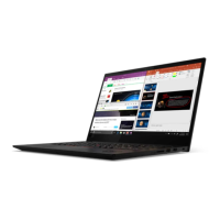
Identifies front controls and connectors for the ThinkPad X1 Carbon Gen 12.
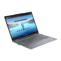
Identifies front controls and connectors for the ThinkPad X1 2-in-1 Gen 9.
Diagrams of computer side views showing ports and connectors.
Illustration of the computer's bottom view, including the emergency-reset hole.
Information on identifying Field Replaceable Units (FRUs) and Customer Replaceable Units (CRUs).
Diagram and list of major Field Replaceable Units and Customer Replaceable Units.
List and descriptions of miscellaneous parts kits and screw kits.
Helps technicians identify connectors and cables for replacement purposes.
Guide to system board connectors, internal cables, and their connections.
Connectors for trackpad, fingerprint reader, P sensor, and NFC modules.
Instructions on how to find detailed FRU information on the Lenovo support website.
List of tools required for servicing the notebook computer.
Information on special nylon-coated screws and proper tightening methods.
Steps to perform sensor calibration after system board or LCD unit replacement.
Instructions for retaining and restoring serial numbers and UUIDs.
Procedure to restore the system unit's serial number after board replacement.
Procedure to create a new Universally Unique Identifier (UUID) for a system board.
How to read or write Engineering Change Announcement (ECA) information.
General guidelines and precautions for removing or replacing any Field Replaceable Unit (FRU).
Important topic to read carefully before performing any service on the computer.
Steps to disable the built-in battery before performing FRU replacement.
Procedure to remove the nano-SIM card and its tray.
Removal steps for the base cover assembly.
Procedure for removing and replacing the built-in battery.
Steps to remove and replace the M.2 solid-state drive and its bracket.
Procedure to remove and replace the Wireless WAN card.
Removal and installation steps for 4G wireless WAN cards.
Removal and installation steps for 5G wireless WAN cards.
Procedure for models with wireless WAN card bracket only.
Antenna cable routing for 4G wireless WAN cards with 4 connectors.
Antenna cable routing for 5G wireless WAN cards.
Steps to remove and replace the thermal fan assembly.
Steps to remove and replace the speaker assembly.
Steps to remove the trackpad, fingerprint reader, P sensor, and NFC cable.
Steps to remove the wireless WAN antenna assembly.
Steps to remove the wireless WAN antenna cable guide rubber.
Steps to remove and replace the coin-cell battery.
Steps to remove and replace the fan cable guide.
Steps to remove and replace the USB bracket.
Steps to remove the NFC module and NFC sponge.
Steps to remove the trackpad/haptic touchpad and its spill mylar.
Steps to remove and replace the system board and SSD thermal pad.
Detailed steps for removing the system board.
Steps to remove and replace the LCD unit.
Steps to remove and replace the keyboard assembly.
List of trademarks and registered trademarks for Lenovo and other companies.