- 8 -
ThinkSystem RAID 930-16i 8GB Flash PCIe 12Gb/s Adapter Installation and User Guide
Version 1.0
Chapter 2: Overview
Adapter Characteristics
2.4.3 Board Layout, LEDs, Jumpers, and Connectors
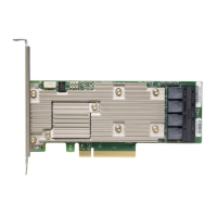
The ThinkSystem RAID 930-16i adapter is 6.127 in. × 2.712 in. (155.65 mm × 68.90 mm) boards. The component height
on the top and bottom of the adapter complies with the PCIe specification. This section provides the board layout, and
the LED, connector, and jumper information for the adapter.
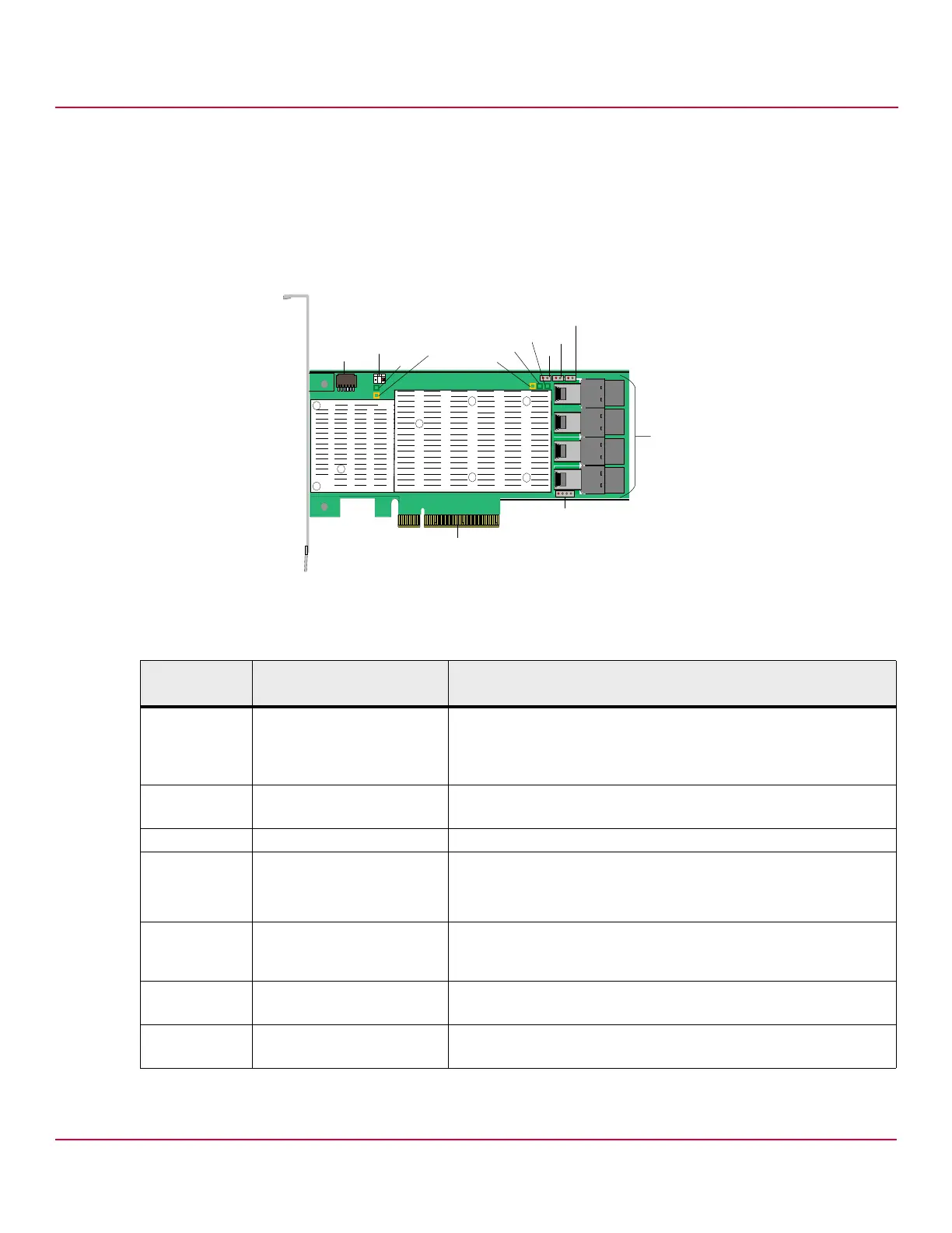
The following figure shows the LEDs, jumpers, and connectors on the adapter.
Figure 2 Board Layout for the ThinkSystem RAID 930-16i Adapter
The following table describes the LEDs, jumpers, and connectors on the adapter.
Table 1 LEDs, Jumpers, and Connectors
Jumper/
Connector
Type Description
J2 Standard edge card connector The interface between the adapter and the host system.
With the PCIe interface, this connector provides power to the board and an
I
2
C interface connected to the I
2
C bus for the Intelligent Platform
Management Interface (IPMI).
J4 Default serial boot ROM (SBR)
header
2-pin connector.
Reserved for Lenovo debug.
J7 Reserved for Lenovo debug 3-pin connector. Reserved.
J8 On-board serial Universal
Asynchronous
Receiver/Transmitter (UART)
connector
4-pin connector.
Reserved for Lenovo debug.
J10 Global hard disk drive (HDD)
activity LED header
2-pin connector.
Connects to an LED that indicates activity on the drives connected to
the adapter.
J11 Global drive fault LED header
serial
2-pin connector.
Connects to an LED that indicates whether a drive is in a fault condition.
J14 ThinkSystem RAID 930 SuperCap
interface
9-pin connector.
Connects the adapter to a ThinkSystem RAID 930 SuperCap.
*
*
*
*
?
*
*
*
*
,%$
,%$
,%$
,%$
,%$
#
#
#
#
*
 Loading...