Page 6
I-UNIT COMPONENTS
ML180UHA unit components are shown in figure 1.The
gas valve, combustion air inducer and burners can be ac
cessed by removing the upper access panel. Electrical
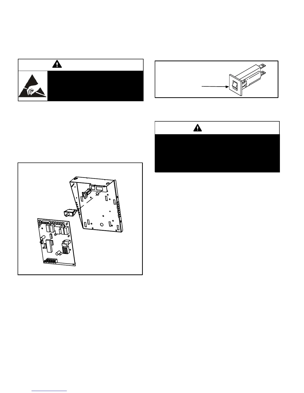
components are in the control box (figure 2) found in the
blower section.
CAUTION
Electrostatic discharge can affect elec
tronic components. Take precautions
to neutralize electrostatic charge by
touching your hand and tools to metal
prior to handling the control.
1. Control Transformer (T1)
A transformer located in the control box provides power to
the low voltage section of the unit. Transformers on all
models are rated 40VA with a 230V primary and a 24V sec
ondary.
2. Door Interlock Switch (S51)
A door interlock switch rated 14A at 230VAC is wired in se
ries with line voltage. When the blower door is removed the
unit will shut down.
FIGURE 2
CONTROL BOX ML180UHA
Integrated Control
Door Interlock Switch
3. Circuit Breaker (CB8)
A 24V circuit breaker is also located in the control box.
The switch provides overcurrent protection to the trans
former (T1). The breaker is rated 3A at 32V. If the current
exceeds this limit the breaker will trip and all unit opera
tion will shutdown. The breaker can be manually reset
by pressing the button on the face. See figure 3.
FIGURE 3
CIRCUIT BREAKER CB8
PRESS TO RESET
4. Integrated Control (A92)
WARNING
Shock hazard.
Disconnect power before servicing. Control is not
field repairable. If control is inoperable, simply re
place entire control.
Can cause injury or death. Unsafe operation will re
sult if repair is attempted.
The hot surface ignition control system consisting of an in
tegrated control (figure 4 with control terminal designa
tions in tables 1 and 2.) sensor and ignitor (figure 6). The
integrated control and ignitor work in combination to en
sure furnace ignition and ignitor durability. The integrated
control, controls all major furnace operations. The inte
grated control also features one LED light (AN1 red) for
troubleshooting and two accessory terminals rated at (1)
one amp. The integrated control also features a (3) amp
fuse for overcurrent protection. See table 3 for trouble
shooting diagnostic codes. The nitride ignitor is made
from a non-porous, high strength proprietary ceramic ma
terial that provides long life and trouble free maintenance.
The integrated control continuously monitors line voltage
and maintains the ignitor power at a consistent level to
provide proper lighting and maximum ignitor life.


 To Next Page
 Loading...