506305-01 Page 21 of 36Issue 0938
Be sure that the pressure switch hose does not form a
trap to hold condensation that could form from the flue
gas. Hose may be cut shorter to avoid forming a trap, if
required.
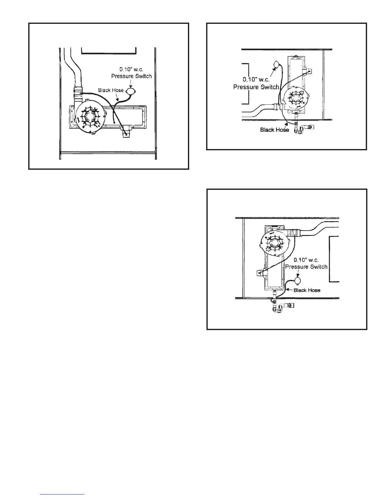
Horizontal Installation
The G1D91BT and G1D93BT multi-position units are
shipped from the manufacturer with a black hose having
one end connected to the 0.10” drain pressure switch and
the other end shipped loose. FOR HORIZONTAL
INSTALLATIONS the loose end MUST be connected to the
external drain trap.
Route hose through gas line access hole in cabinet. Then
connect to 1/4" barbed fitting on drain trap assembly.
For right to left airflow installations, see Figure 32. For left
to right airflow installations, see Figure 33.
Be sure that the pressure switch hose does not form a
trap to hold condensation that could form from the flue
gas. Hose may be cut shorter to avoid forming a trap, if
required.
Pressure Switch Connection
Upflow Installation
Figure 31
Pressure Switch Connection
Horizontal Installation – L to R Airflow
Figure 33
Pressure Switch Connection
Horizontal Installation – R to L Airflow
Figure 32
 Loading...