26 Information LR101
7.3 Resetting the LR101
These settings can be initiated at any time while the Digital plus system is in
operation and the LR101 is connected (regardless of whether the LR101 is
connected to its own separate power supply or to terminals J and K). Press the
push button on the LR101 and keep it pressed until the following procedure is
completed:
After 5 seconds, the LED begins to shine. Wait until the flashing stops and the
LED goes out. Now release the button. The LR101 is reset to its factory settings.
8 Connecting the LR101
You can either supply the LR101 with DC (terminals J and K of the amplifiers
LZV100/LZV200, LV100, LV101, LV102, LV103 or LV200) or AC (12 - 16V).
Terminals R and S are the connections for the feedback bus. These terminals are
connected to the terminals of the LZ100/LZV100/LZV200. Several LR101/LR100
are simply connected in parallel. Please refer to Figure 5.
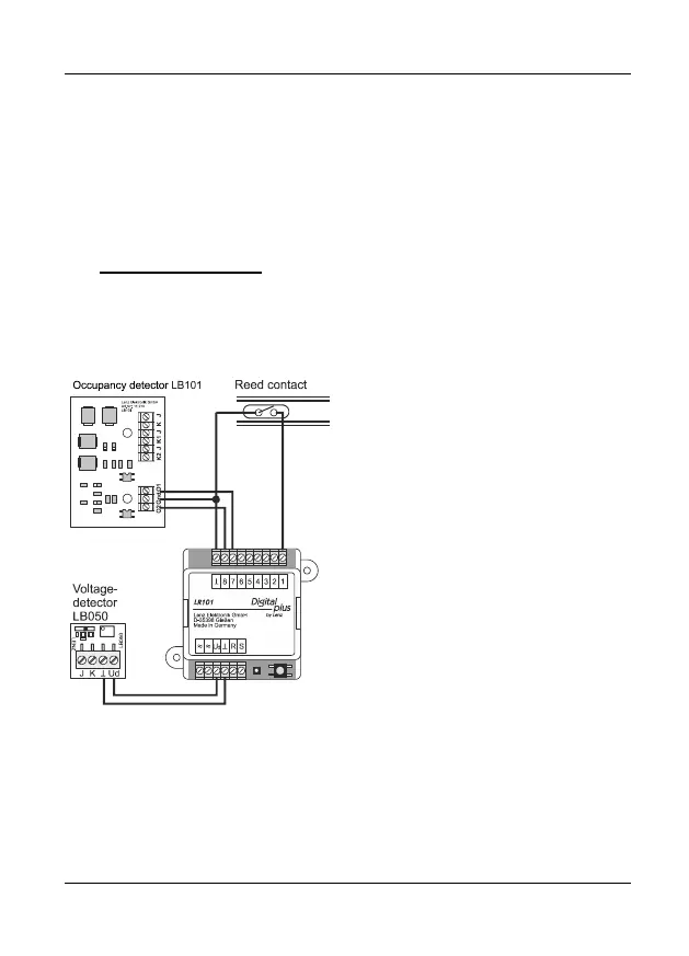
Figure 4: Connecting signal devices
Digital plus occupancy detectors
LB100/LB101 and other voltage-free
contactors can be used as signal
devices for the transmission of status
information. For the connection of
signal devices, please refer to
Figure 4 which illustrates the wiring of
the LR101 and the signal devices. For
the complete connection of the
occupancy detector LB100/LB101 and
the voltage detector LB050, please
refer to the individual operating
manuals.
 Loading...