28 Information LR101
Warning:
You may not use track contacts that create connections to the track
voltage as these will destroy the LR101!
The
terminals of several LR101 may not be connected to each other as
you are not dealing with continuous mass!
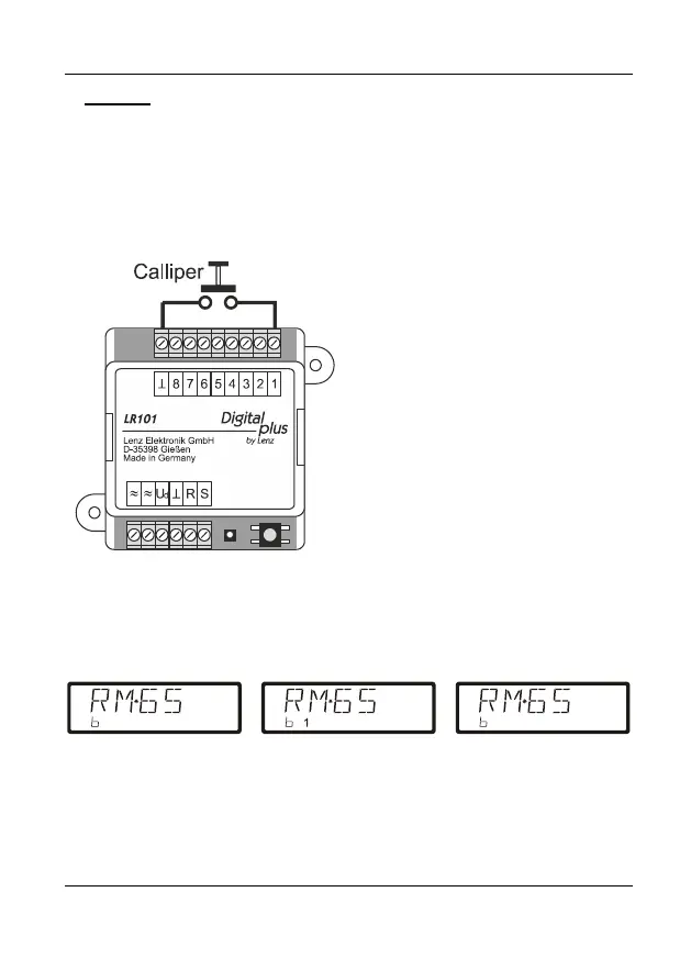
8.1 Experimental setup for the operation of the LR101
Installation, programming and wiring
can be easily tested:
Simply connect a calliper to signal
input 1, as shown in Figure 6. The
function 'Read out feedback' of the
handhelds LH100 or LH101 is well
suited for testing the correct wiring and
programming of the LR101. Status
changes of the calliper can be read
out on the display of the
LH100/LH101. Our example assumes
that ex-works the LR101 is set to
address 65.
Change the mode of the handheld to
'Read out feedback' and select
feedback address 65.
The display of the handheld (i.e LH100) will change depending on whether the
calliper is open or closed:
If you have set a delay for input 1, you will be able to monitor this delay on the
display of the LH100.