22 Accessory Decoder LS 100/110
Trouble shooting
Problem Cause Solution
Turnout does not throw, the
LED does not flicker while a
entered.
Enter the correct turnout
address.
switching command is being
sent (a switching command is
always sent when you press
the ‘+’ or ‘-’ key on LH100 while
Connection between command
station and power station or
between power station and
accessory decoder is broken.
connections.
in switching mode, or when on
LW100 one of the red or green
keys is pressed).
A power station has turned off
due to a short circuit or user
OFF.
Remove cause of the short
circuit, in case of an overload,
divide the layout into several
supply sections.
External power supply is not
connected (terminals ‘≈≈' are not
connected).
(see illustrations 2 and 1).
Turnout does not throw, but the
LED flickers while a switching
command is being sent.
Turnout or signal drive is not
correctly connected, or is
defective.
connections.
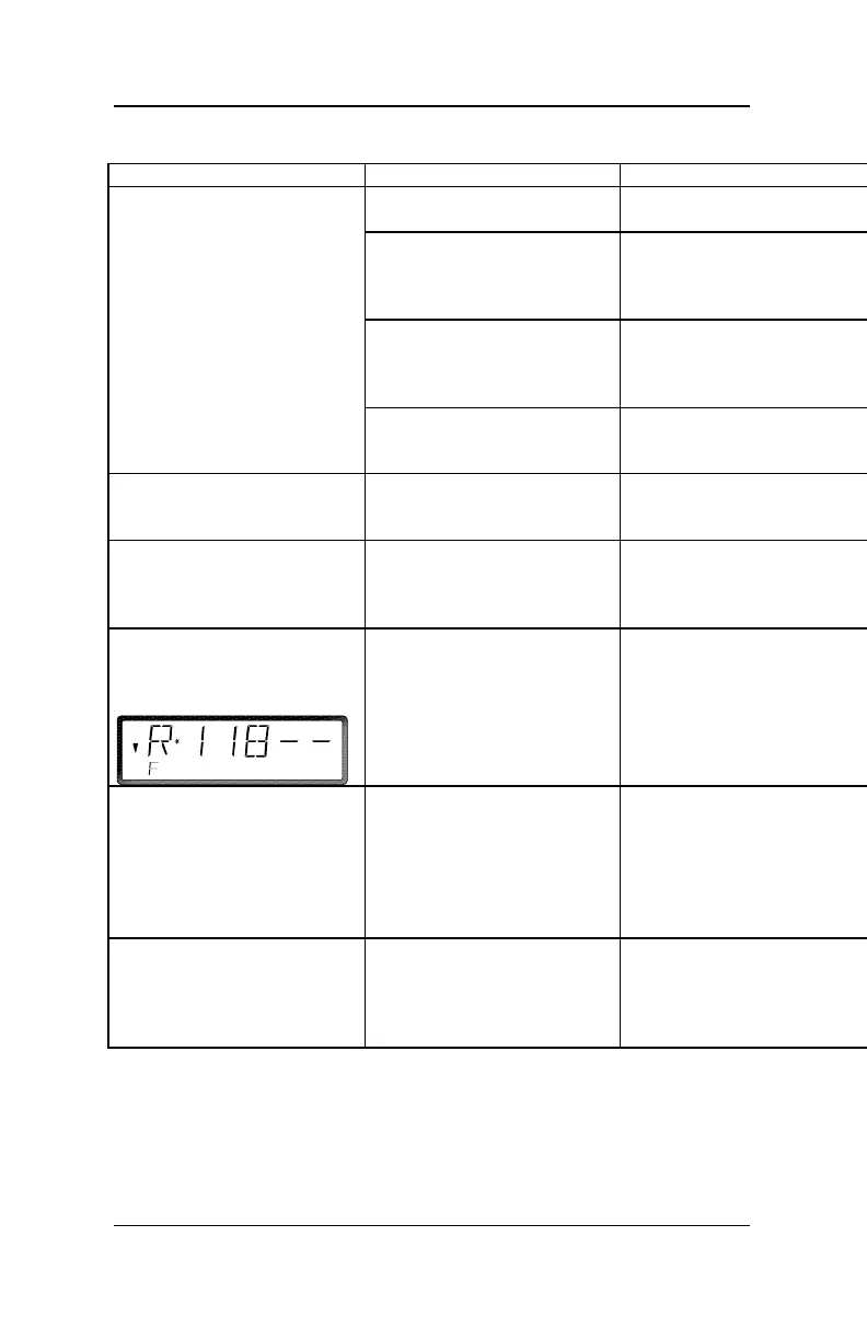
A called up LS100 is not shown
as a feedback capable decoder
display).
Feedback bus is not connected
switched.
Connect the feedback bus, or
correct the wires.
LS100/LS110 on LH100, the
shows:
The entered address is not
decoder, but by a feedback
encoder.
Enter the correct turnout
overlapping addresses (see
“The shared address area of
LR100) earlier in this manual.
When programming from the
programming output of the
command station, you get the
hand held controller.
The command station cannot
programming, since no load is
connected to the output of
LS100/LS110.
Connect a turnout drive or
lightbulb to one of the outputs
address and settings through
the programming output of
LZ100” earlier in this manual.
When programming from the
programming output of the
command station, you get the
hand held controller.
programming output of the
command station (terminals P
and Q) and LS100/LS110 is not
correct.
connections.


 To Next Page
 Loading...