6 Accessory Decoder LS 100/110
DCC system and does not use a separate power supply line to
power the LS100/110. The second option uses an external
power supply to power the LS100/110. Illustrations 1 and 2 show
the connection using the LS110. The LS100 is connected in the
same way, using the same terminals.
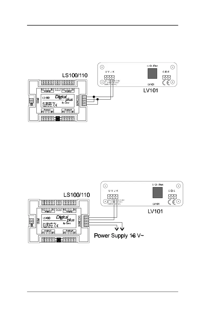
Illustration 1: Connecting an LS100/110 to an LV100/101 using a
separate power supply line (LS100 shown)
Illustration1 demonstrates the method of connecting an
LS100/LS110 to the track outputs of a power station. Terminals
'
≈≈' are here connected in parallel with terminals J and K to
LV100/101. With this option all the power required to operate
the devices connected to the LS100/110 is supplied by the DCC
power station.
Illustration 2: Connecting an LS100/110 to an LV100/101
(LS100 shown)
Illustration 2 shows how to conect the LS100/110 to an external
power supply. Terminals K and J of the LS100/LS110 are