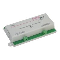
8 LT100 Digital Circuit Breaker
From this follows that a LED must be connected with its cathode
to the output (1 to 32) and with its anode to the “++++” terminal. It
makes no difference if you install the necessary current limiting
resistor on the cathode or anode side; just remember that each
LED needs its own resistor.
The following table is a guide for determining the value of the
resistor. The values listed apply when using a voltage supply of
16V.
LED current Resistor
3 mA 5.6 kOhm
5 mA 3.3 kOhm
10 mA 1.5 kOhm
Components for display control panels
If you use ready-made components to build your display control
oanel, you must make note of this:
The lights in the components (lightbulbs or LEDs) must not
exceed the allowed maximum current of 50mA per output!
If the components have LEDs installed in them, you need to
ensure that the required resistors are present as well. If they are
not, you must connect them in addition.
Ready-made components often have 2 LEDs connected together.
In this case these LEDs must be joined at their anodes, and each
LED needs to have its own resistor, or it must be possible to add
one afterwards!
Hüttenbergstraße 29
Fax: 06403 5332
www.digital-plus.de
http://www.lenz.com
Lenz Agency of North America
PO Box 143
Chelmsford, MA 01824
ph: 978 250 1494
fax: 978 455 LENZ
support@lenz.com
This equipment complies with Part 15 of FCC Rules. Operation is subject
to the following two conditions: (1) this device may not cause
harmful interference, and (2) this device must accept any interference received,
including interference that may cause undesired operation.
Please save this manual for future reference!
© 2000 Lenz GmbH, All Rights Reserved
 Loading...