SF01U 21
11.2 TWO-WIRE START/STOP CONTROL
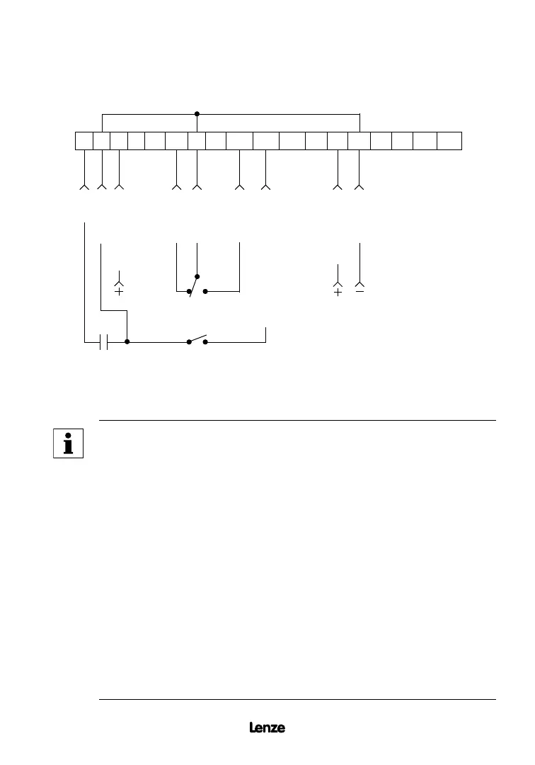
Shown below is the wiring diagram for a typical two-wire start/stop control scheme, using one
maintained contact (such as that from a PLC) for RUN and STOP commands.
MAINTAINED
RUN/STOP
CONTACT
1 2
5 6
12
TXA TXB
2 13A 13B 13C14 15 2
STOP
COMMON
0-10 VDC INPUT
COMMON
FORWARD
REVERSE
0-10 VDC or 4-20 mA SELECT
COMMON
4-20 mA INPUT
11 25 31
30
The TB-2 terminals are internally connected to each other
NOTE
• Close TB-1 to TB-2 to RUN, and open TB-1 to TB-2 to STOP
• If reverse direction is also required, ROTATION DIRECTION (Parameter
17) must be set to FORWARD AND REVERSE (02), and TB-13A
(Parameter 10) must be set to START REVERSE (06). If reverse
direction is not required, TB-12 must be wired directly to TB-2.
• For 0-10 VDC or 4-20 mA speed control, use one of the following
methods:
- Program one of the TB-13 terminals (13A, 13B, or 13C) for 0-10
VDC (02) or 4-20 mA (03). When that TB-13 terminal is closed to
TB-2, the drive will respond to the selected speed reference signal.
If that TB-13 terminal is not closed to TB-2, the drive will respond to
the speed control source selected in Parameter 05 - STANDARD
SPEED SOURCE. This method must be used if it is necessary to
toggle between two speed sources.
- Program Parameter 05 - STANDARD SPEED SOURCE for 0-10 VDC
(03) or 4-20 mA (04). This method is preferable if only one speed
source is required, as this method leaves the TB-13 terminals free to
be used for other functions.
Artisan Technology Group - Quality Instrumentation ... Guaranteed | (888) 88-SOURCE | www.artisantg.com
 Loading...