SF01U 19
NOTE
If TB-13A, TB-13B, and TB-13C are all programmed to select speed references,
and two or three of the terminals are closed to TB-2, the higher terminal has
priority and will override the others. For example, if TB-13A is programmed
to select 0-10VDC, and TB-13C is programmed to select PRESET SPEED
#3, closing both terminals to TB-2 will cause the drive to respond to PRESET
SPEED #3, because TB-13C overrides TB-13A.
The exception to this is the MOP function, which requires the use of TB-13B
and TB-13C. This leaves TB-13A to be used for some other function. If TB-
13A is programmed for a speed reference, and TB-13A is closed to TB-2,
TB-13A will override the MOP function.
10.7 ANALOG OUTPUT SIGNALS
Terminal TB-30 can provide a 0-10 VDC or a 2-10 VDC signal proportional to output frequency
or load, and TB-31 can provide the same signals proportional to load only. The 2-10 VDC
signal can be converted to a 4-20 mA signal using a resistor in series with the signal such
that the total load resistance is 500 Ohms. Refer to Parameters 08 and 09 in Section 15.0
- DESCRIPTION OF PARAMETERS.
NOTE
These analog output signals cannot be used with “loop-powered” devices that
derive power from a 4-20 mA signal.
10.8 DRIVE STATUS DIGITAL OUTPUTS
There are two open-collector outputs at terminals TB-14 and TB-15. The open-collector circuits
are current-sinking types rated at 30 VDC and 50 mA maximum.
The open-collector outputs can be programmed to indicate any of the following: RUN, FAULT,
INVERSE FAULT, FAULT LOCKOUT, AT SPEED, ABOVE PRESET SPEED #3, CURRENT
LIMIT, AUTO SPEED MODE, and REVERSE. Refer to Parameters 06 and 13 in Section 15.0
- DESCRIPTION OF PARAMETERS.
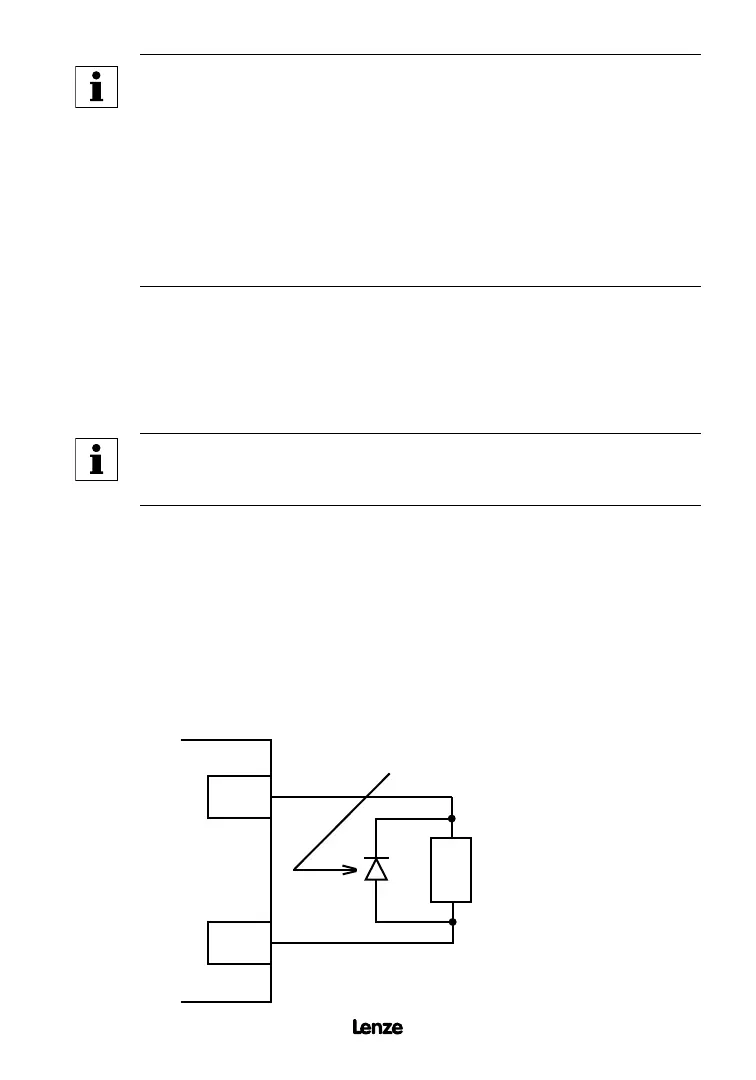
The diagram below illustrates how the 12 VDC power supply at TB-11 can be used with the
open- collector output to drive an external relay:
TB-11
TB-14
SCF TERMINAL STRIP
RELAY COIL
DIODE SNUBBER
(1N4148 or Equivalent)
Artisan Technology Group - Quality Instrumentation ... Guaranteed | (888) 88-SOURCE | www.artisantg.com