Mechanical installation
Mounting of g500 short/servo adapters with clamping connection
Maximum permissible load at the motor adapter
4
29
Lenze ¯ MA 12.0018 ¯ 4.1
8
7
2
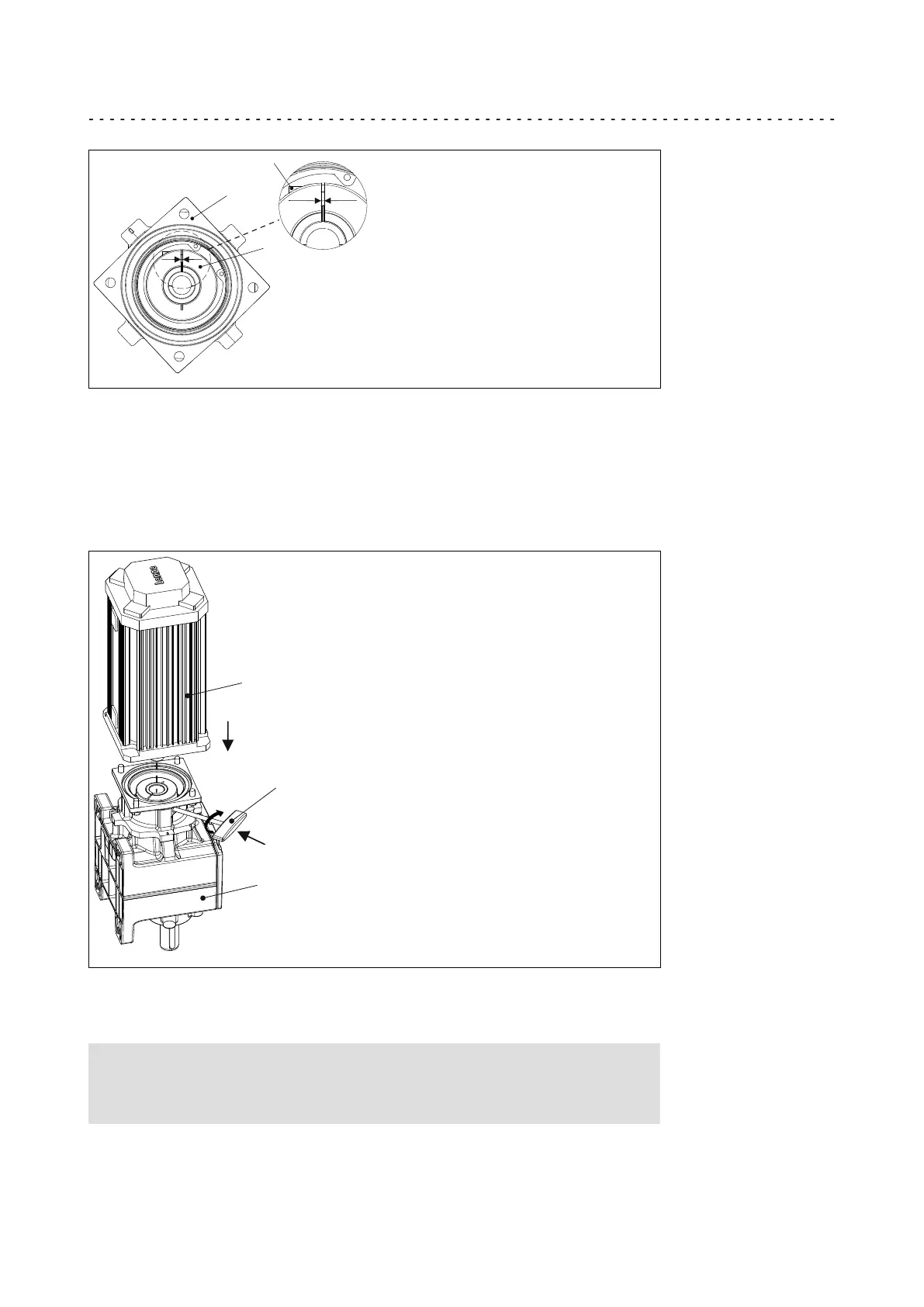
Fig. 6 Assignment: Motor shaft, clamping ring and mounting hole
2 Bell housing 7 Clamping ring
8 Terminal screw
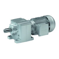
4. Afterwards, insert the wrench (9) into the terminal screw (8) of the clamping ring
(7) and leave it there (Fig. 7). The terminal screw (8) must only be tightened to
such a degree that the clamping ring (7) does not move but the shaft is not
tightened yet!
1.
3.
2.
1
9
3
Fig. 7 Mounting of motor and gearbox
1 Gearbox 9 Wrench
3 Motor
Stop!
If the motor shaft is provided with a keyway, align the motor shaft in
such a way that the keyway is located opposite to the terminal screw.