Determinaon of the required gearbox load capacity
Dene the required load factor at runme t
L
Runme t
L
≤ 10 % Take the load factor k from diagram into account
Runme t
L
> 10 % Take intensity k
I
from calculaon into account
Calculate intensity
no alternang load k
I
= M
L,max
/ M
L
k
I
=
at alternang load k
I
= M
L,max
/ M
L
x 1.4 k
I
=
Load factor k
0 1 2 3 4 5 6 7 8 9 10 %
1.0
1.5
2.0
2.5
3.0
3.5
4.0
4.5
1.3 1.2
1.5
1.7
1.9
2.1
2.3
2.5
2.7
2.9
3.1
3.3
3.5
3.7
3.9
4.1
4.3
4.5
4.7
1.4
1.6
1.8
2.0
2.2
2.4
2.6
2.8
3.0
3.2
3.4
3.6
3.8
4.0
4.2
4.4
4.6
24 h 16 h 8 h
k = 5
I
k = 4
I
k = 3
I
k = 2
I
I
II
III
IV
t
L
k
Operang mode S1
Calculaon of the required drive power
Calculaon Result Unit
Output torque M
R
≥ M
L
/ (k
L
x k
H
) M
R
= Nm
Output speed n
R
≥ n
L
/ k
E
n
R
=
rpm
Drive power P
R
≥ M
R
x n
R
/ 9549 p
R
=
kW
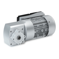
Check geared servo motor and determine from the selecon table
Check Selecon Unit
Drive power P
1
≥ P
R
p
1
=
kW
Output torque M
2
≥ M
L
M
2
= Nm
Output speed n
2,th
≥ n
L
n
2,th
=
rpm
Load capacity of the geared motor c ≥ k
c ≥ k
I
c =
Short-me maximum torque
no alternang load M
2,max
≥ M
L,max
M
2,max
= Nm
at alternang load M
2,max
x 1.5 ≥ M
L,max
M
2,max
= Nm
Rao
i =
4Selecon tables ^ 64
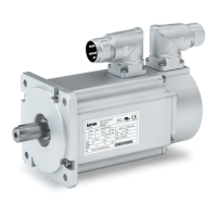
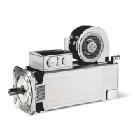
Informaon on project planning
Drive dimensioning
26

 Loading...