Product description
Cabinet PC (CPC) design
CPC 5100
3
l
26
EDSIPCx7 EN 4.1
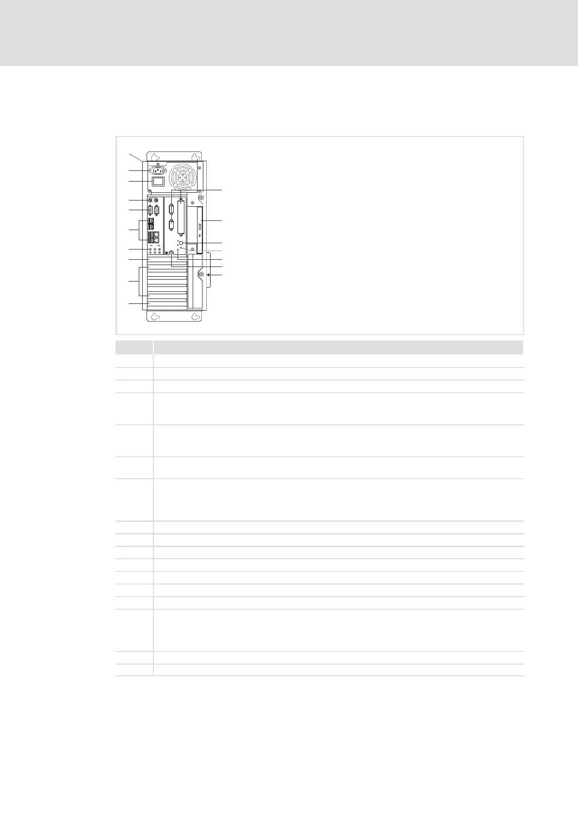
3.6.3 CPC 5100
Elements
AUDIO
VGA
MIC
USB
USB
INOUT
LAN
MOUSE
COM1
KEYB
X 2
X 1
POWER
STANDBY
HD
RESET
CTRL
SLOTABCDEFG
I
0
<
=
>
?
@
0
1
2
3
4
5
7
6
9
8
;
:
CPC5100−001
Pos. Description
0 Control cabinet PC
1 Mains connection 115 ... 230 V AC
2 Mains switch
3 From left to right:
l Keyboard connection (PS/2)
l Mouse connection (PS/2)
4 From left to right:
l Analog monitor connection (VGA)
l Serial interface (COM1)
5 8 x USB−A
2 x Ethernet (RJ45)
6 From left to right:
l Microphone
l Audio line−out
l Audio line−in
7 Digital monitor connection (DVI on PCIe expansion card)
8 5 x PCI slot
9 PCIe x4 slot (in x16 socket)
: Optionally assigned interfaces
; DVD drive (option)
< Stand−by pushbutton
= Reset pushbutton
> From the top to the bottom:
l Power LED (is lit if mains voltage is applied)
l HD−LED (is lit if the hard disk is accessed)
l CTRL−LED (green: housing fan in operation; red: housing fan out of service)
? PE terminal screw (protective conductor)
@ Labelling field for the terminal and slot assignment