EasyManua.ls Logo

Leroy-Somer unidrive sp User Manual

Leroy-Somer unidrive sp
108 pages
To Next Page IconTo Next Page
Page #1 background imageLoading...
Page #1 background image
SM-PROFIBUS DP-V1SM-PROFIBUS DP-V1
User guide
4442 en - 2009.11 / a
This manual is to be given
to the end user
Solutions module forSolutions module for
fieldbus communication fieldbus communication
READ
Start
Send first telegram
to OUT word 0
Read IN
word 0
Tx_Stamp_No =
Rx_Stamp_No?
Send next
telegram to
OUT word 0
Tx_Stamp_No
= 2?
No
Yes
Check status
of ERR bit
1
0
ERROR. Check paramter exists, data
is in correct range, and parameter is
Read/Write
Calculate
data value
END OF
SEQUENCE
Read IN
word 0
Tx_Stamp_No =
Rx_Stamp_No?
Send next
telegram to
OUT word 0
Tx_Stamp_No
= 6?
No
Yes
Send telegram 3 to
OUT word 0
Store data
byte
Yes
No
Yes
No
DIGITAX ST
UNIDRIVE SP
AFFINITY
MENTOR MP
DIGIDRIVE SK
R
E
A
D
S
t
a
r
t
r
r
S
e
nd
i
r
s
t
t
e
l
eg
r
a
m
t
o
O
U
T
w
o
r
d
0
R
ea
d
I
N
TOR
MP
R
IVE
S
K

Table of Contents

Other manuals for Leroy-Somer unidrive sp

Question and Answer IconNeed help?

Do you have a question about the Leroy-Somer unidrive sp and is the answer not in the manual?

Leroy-Somer unidrive sp Specifications

General IconGeneral
Overload CapacityUp to 150% for 60 seconds
HumidityUp to 95% non-condensing
Output Voltage0 to Vin
CommunicationModbus, CANopen, Profibus, Ethernet
ProtectionOvercurrent, Overvoltage, Undervoltage, Overtemperature, Short Circuit
Enclosure RatingIP20, IP66
Ambient Temperature-10°C to +40°C
AltitudeUp to 1000 m without derating

Summary

1 Safety Information

1.2 Electrical Safety - General Warning

General warning about severe electrical shock hazards associated with drive operation.

1.3 System Design and Safety of Personnel

Guidance on system design, installation, and safety precautions for personnel working with the drive.

1.7 Adjusting Parameters

Cautionary advice on adjusting parameters that significantly affect drive operation and system control.

2 Introduction

2.2 What is SM-PROFIBUS DP-V1?

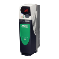
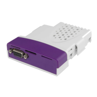
Description of the SM-PROFIBUS DP-V1 module and its compatibility with LEROY-SOMER drives.

2.3.2 Main Differences Between DP-V0 and DP-V1

Highlights key differences and features supported by PROFIBUS DP-V1 compared to DP-V0.

3 Mechanical Installation

3.1 General Installation

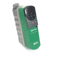
Illustrates the physical installation process of a Solutions Module into a drive slot.

4 Electrical Installation

4.1 Terminal Descriptions

Details the SM-PROFIBUS DP-V1's D-type connector and pin assignments for network connection.

4.6 Network Termination

4.7 Maximum Network Length / Device Loading

4.8 Node Addressing

5 Getting Started

5.2 Minimum Software Versions Required

Lists minimum required software versions for drive and module compatibility.

5.3 Set-up Flow Chart

5.4 Node Address

5.5 Network Data Rate

5.6 Data Format

5.7 Network Operating Status

5.8 Re-initializing the SM-PROFIBUS DP-V1

5.9 Re-initialize all Solutions Modules

5.10 Saving Parameters to the Drive

5.11 Network Compatibility Mode

6 GSD Files

6.2 Data Consistency

Discusses potential data skew issues and the 'data consistency' feature for reliable data transfer.

6.3 Data Configuration

7 Cyclic Data

7.1 What is Cyclic Data?

Explanation of cyclic data transfer as polled data for high-speed drive communication.

7.2 Data Formats

Details on configuring cyclic data formats and mapping parameters for IN/OUT data words.

7.3 Mapping Conflicts

7.4 Cyclic Data Mapping Errors

8 Non-Cyclic Data

8.2 Configuration Using Non-Cyclic Data

8.4 PROFIBUS DP-V1 Overview

8.5 Setting the Non-Cyclic Mode (Non-Cyclic over Cyclic)

8.6 Mode 1 - CT Single Word Mode

8.6.2 CT Single Word Protocol

8.7 Reading Parameters Using CT Single Word

8.7.1 Constructing CT Mode 1 Single Word Read Messages

8.7.3 Writing Parameters Using CT Single Word

8.8 Mode 2 - PPO 4 Word Mode

8.8.2 PPO 4 Word Protocol

8.8.3 Reading Parameters Using PPO 4 Word Mode

8.8.4 Writing Parameters Using PPO 4 Word Mode

9 Control and Status Words

9.2 Control Word

Details the sixteen control bits of the SM-PROFIBUS DP-V1 control word and their functions.

9.3 Status Word

10 Diagnostics

10.3 PROFIBUS-DP Node Address

10.4 Network Data Rate

10.5 Data Format

10.6 Operating Status

10.7 Mapping Status

10.9 Module Error Code

10.11 Troubleshooting

Figure 10-1 Diagnostic Flow Chart

11 PROFIdrive Profile (V4)

11.3 Main Setpoint

11.4 Main Actual Value

11.5 PROFIdrive (V4) State Machine

11.6 Normal Run Sequence

Figure 11-1 PROFIdrive V4 General State Machine Diagram

Figure 11-2 PROFIdrive V4 Speed Control State Machine

11.7 Stopping the Motor Using PROFIdrive

11.8 Jogging

11.9 PROFIdrive Control Word

11.10 PROFIdrive Status Word

11.11 PROFIdrive PNU Access

11.12 Fault Buffer

12 Advanced Features

12.1 Network Loss Trip

Configuration and function of the network loss trip feature for communication monitoring.

12.2 SYNC and FREEZE Mode

12.5 Cyclic Data Compression

12.6 Block Mapping

12.7 Direct Data Mapping

12.9 Restore Defaults

12.10 Storing SM-PROFIBUS DP-V1 Parameters (Backup)

12.11 Restore Previous SM-PROFIBUS DP-V1 Configuration

12.12 Menu 60 - Local Solutions Access

12.13 Mapping to SM-Applications Parameters

13 Legacy Features

13.2 PPO Types

13.3 Configuring the Profile

13.4 PROFIdrive Control Word

13.5 PROFIdrive Status Word

14 Quick Reference

14.1 Complete Parameter Reference

Lists all SM-PROFIBUS DP-V1 setup parameters with cross-references and descriptions.

14.2 Operating Status Codes

14.3 Mapping Error Codes

14.4 Error Codes

15 Glossary of Terms

Related product manuals