APPENDIX A
WIRING MULTIPLE DEVICES
IN SERIES WITH THE PMC-1
10
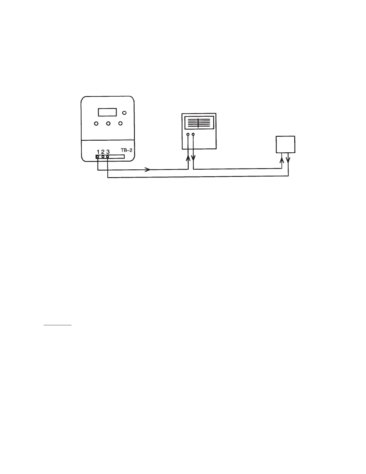
The PMC-1 is provided with a 4-20mA output for recorders,
alarms, etc. It may be possible to overload the 4-20mA
output, and additional devices need to be powered in series.
The purpose of this Appendix is to provide guidelines for
wiring another device, such as a chart recorder, in series
with the PMC-1 and a transmitter.
The acceptability of such a practice is based on the following
rule: The total voltage drop of all devices in the circuit must
be less than the output voltage of the power supply.
The PMC-1’s power supply puts out a total of 24 VDC to the
transmitter circuit. As stated in the specifications, the input
resistance of the PMC’s transmitter circuit is 100Ω. Using
Ohm’s law, the voltage drop at 20mA (.020 Amps) can be
calculated as follows:
Voltage (V)
= Resistance (R)
Current (I)
Voltage = Resistance x Current
Voltage = 100 x .020 + 0.7
Voltage = 2.7 Volts
Thus, at 20mA, the voltage drop of the PMC’s transmitter
loop is 2.7 volts.
EXAMPLE:
The PMC-1 is being used in a level control application. The
differential pressure transmitter used to measure the level
has a minimum power requirement of 12 volts. A chart
recorder with an impedance (resistance) of 450Ω is being
considered for use with the level control system. Can the
chart recorder be wired in series with the PMC-1 and dp
transmitter?
Voltage (Chart Recorder) = 450Ω x .020 = 9 V
Total Voltage = 2.7(PMC-1) + 12(dp Transmitter) +
9(Chart Recorder)
Total voltage = 23.7 V
Since the total voltage is less than the 24 volt output of the
power supply, the chart recorder can be wired in series with
the PMC-1 and dp transmitter.
Note: Long lengths of wire can result in additional resistance
in the loop and must be considered when the total voltage
drop from all devices in the loop approaches the voltage of
the power supply output. When in doubt, consult Leslie for
assistance.
PMC-1
Recorder
(4-20mA Input)
Transmitter
 Loading...