CD 617 ISSUE 1 : 27/07/2020
16. PRE-CHECK INFORMATION:
A. Door Zone Sensor / Door Zone Actuators Fitted At Each Floor Level.
a. Ensure Door Zone Actuators (DZA’s) are fitted at each flr lev and operate the Door Zone Sensor
(DZS) fitted on the lift car. Also the DZA’s are clear of any obstructions of the lift car and DZS.
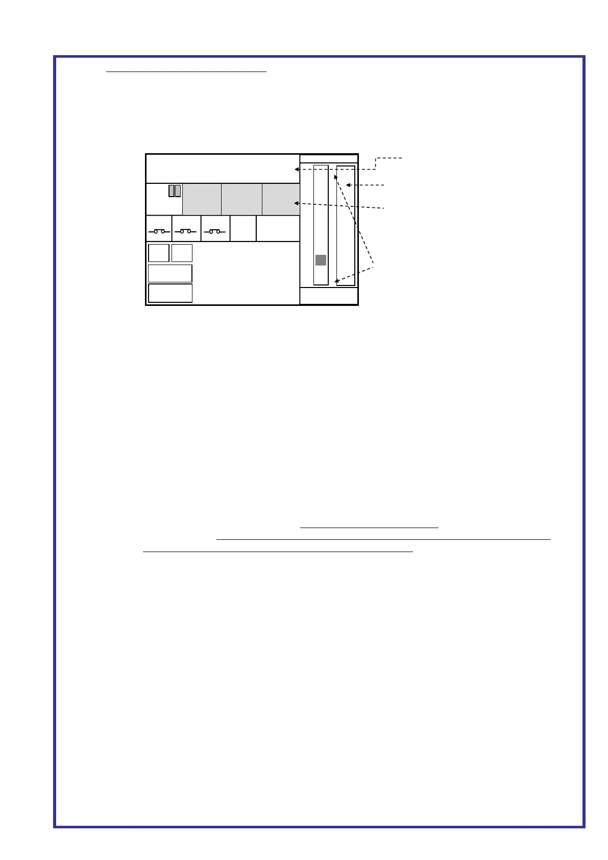
b. Also ensure the signal from the Door Zone Sensor can be seen in the lift controller. This can be
achieved by pressing MAIN MENU then LIFT/GROUP VEIWER on the Almega keypad which
will display the screen as Figs 6/7 below:
B. Motor Wiring / Speed
a. Ensure motor windings and valves are wired correctly. Ensure the motor runs at the correct /
expected speed when on Inspection, Normal and Level Speed. E.g. for 0.3m/s, the Almega LCD
display will show “S = 0.30”, and is the actual measured speed.
C. Almega Parameters
a. TRAVEL SETUP (Press Menu-> PARAMETERS->TRAVEL TIMES)
STOP TIME = 0 Milliseconds
BRAKE RELEASE TIME = 0 Milliseconds
b. POSITIONING SYSTEM SETUP (Press Menu-> PARAMETERS->POSITIONING SYSTEM SETUP)
SPEED PROFILE CONTROL = NO
WITHIN FLOOR LEV DISTANCE = 35mm
LEVEL TO ZERO DISTANCE UP = 25mm
LEVEL TO ZERO DISTANCE DN = 25mm
LEVELLING DISTANCE = 180mm
ACCEL RATE = 1500mm/s^2
SLOW DIST CALC NON PROF CTRL = TRAVEL SPEED PAR
OVRSPEED GOV DIAMETER = Diameter of OSG (i.e. 300mm for Atwell VG OSG)
D. Slowing Limits
a. Ensure slowing limits are set as the backup slowing distances (BSD) as below. (Also see shaft
wiring drawing). Setting the distance too great may generate events "SLOWED: UP/DN SLOW
LIMIT" and result in inaccurate floor levels at the terminal floors!
b. Speed (m/s) BSD (mm) Speed (m/s) BSD (mm) Speed (m/s) BSD (mm)
0.2 = 250 1.0 = 900 2.0 = 2150
0.5 = 450 1.25 = 1200 2.5 = 3000
0.75 = 700 1.6 = 1600 3.0 = 3900
E. Overspeed Governor Encoder (if fitted)
a. Ensure Correction Sensor/Points are firmly fixed and cannot move. Also central to floor level.
b. Ensure the encoder coupling to the OSG is fitted correctly and all the grub screws are tightened.
DZ sensor / Input must be ON!
If the software terminal limit parameter is
set, the terminal limits will appear in the
lift viewer as shown.
Filled RED = no position value assigned
Filled GREEN = limit is ok
Not Filled = limit is broken (on the limit)
Press and Hold the shaft Area for 5
seconds to make the test buttons appear.
VANE
TEST
3 Test Buttons appear in the area
dedicated for extra door operators.
 Loading...